
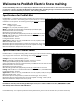
Install Instructions

8
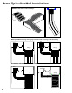
STEP 1.5 (ProMelt Cable only)
If the cable is to be laid on top of an existing slab, select enough Cable Strap to secure the cable to the surface. One
box contains 25 ft. of strap, enough to secure about 50 sq. ft. of cable at 4-ft parallel spacing. Cable strap is usually
spaced no more than 3 to 4 feet apart.
STEP 1.6
Select the controls and sensors for your ProMelt Mats/Cables.
Various types of controls may be used. If you need assistance in selection, see our product catalog or contact your
local dealer or call the factory. Always consult your electrician and designers to ensure proper sizing, location, and site
capabilities.
Refer to the Appendix for typical wire diagrams.
The following guidelines may assist to identify the best solution.
Determine Zoning:
One Zone. In many instances all the areas can be heated at the same time with one control. The control can be
connected to many cables and mats with multiple circuit breakers if needed. One sensor will tell the control when to
operate and when the snow is melted.
Multiple Zones. In some instances it may be preferable to have some areas heated separately from other areas. This
could be the case if you want to snowmelt the sidewalks in front of a store automatically first, then melt rear entrance
areas manually later. In these cases, each “zone” will require its own control and sensor. Do not try to control multiple
zones with one sensor.
Determine Sensing:
Pole-mount sensing. This is the recommended method of sensing moisture and temperature in the area. The PM-2B
and PM-224 are controls with the moisture sensor attached directly on top of the control, so it needs to be mounted on
a conduit in a location that will receive the snowfall on top of the control. The PM-824 control has the moisture sensor
attached to the end of a long length of cable, so this sensor may be mounted on a bracket or conduit away from the
building to receive the snowfall, while the control is mounted on an outside wall. The PM-224 and PM-824 are low-volt-
age and therefore must be used with the Contactor Control. All these controls provide a reliable automatic detection
of the snow and adjustable delay times to allow complete melting of the snow.
In-slab sensing. The PM-HSC5 sensor mounts directly into the slab where snow melting is placed. The location for this
sensor must be chosen carefully to ensure proper operation. This is also a low-voltage sensor and must be used with
the Contactor Control.
Determine Load Size to Select Controls: (Reference Appendix)
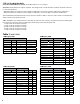
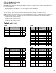
Small Load. Calculate the total “amp draw” of the mats and/or cables you have selected for the zone (see Tables 1 and
2). If the total is 30 amps or less, then you may select one of the following:
A PM-2B control (120VAC, 208VAC, or 240VAC only), for the simplest, direct control.
•
A Contactor Control, and either the PM-224 sensor control or PM-824 sensor control. •
A Contactor Control and an in-slab sensor PM-HSC5. •
Large Load. If the total “amp draw” of the mats and/or cables for the zone is over 30 amps, you may select one of the
following:
A Contactor Control, and either the PM-224 sensor control or PM-824 sensor control.
•
A Contactor Control and an in-slab sensor PM-HSC5. •
STEP 1.7
Consult with your electrician to make sure the mats/cables, control, and design you have selected will work properly.
The ProMelt Mat/Cable and its control must be placed on a dedicated power supply from the circuit breaker
•
panel.
The ProMelt Mat/Cable is a resistance heating system and should be considered as a continuous load for
•
branch circuit sizing purposes.
The circuit breaker must open all ungrounded conductors at the same time. A GFCI type (typically Class B, 30
•
mA trip) is required to directly protect the ProMelt Mat/Cable.