
Install Instructions


10
Phase 2: Preparations
Before installing ProMelt, make sure to fully check out the products, and carefully plan your site. The following steps
may not necessarily occur in the order shown, depending on contractor and electrician scheduling and variations
in site preparation requirements. A good discussion with all parties involved will help eliminate costly errors and
damages.
INSPECT MAT/CABLE, CONTROL, and SENSOR
STEP 2.1
Remove the ProMelt Mat/Cable, control, and sensor from their packages. Inspect them for any visible damage and
verify everything is the correct size and type according to your plan and order. Do no attempt to install a damaged
product.
STEP 2.2
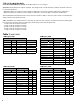
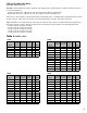
Record the mat/cable information in Table 3. Give this information to the homeowner to keep in a safe place.
The mat/cable model number, serial number, voltage, and resistance range are shown on a nameplate label attached to
the power leads. Do not remove this nameplate label. The electrical inspector will need to see this.
STEP 2.3
Use a digital multi-meter to measure the resistance between the conductors of the mat power leads. Record these
resistances in Table 3 under “Out of the box before installation”.
The resistance between the white lead wires should be within the resistance range on the nameplate label. If it is a
little low, it may be due to low air temperatures or meter calibration. Consult the factory if you are in doubt.
The resistance between the white lead and ground lead should be “open”, usually indicated by an “OL” or whatever
your meter shows when the test leads are not touching anything. If there is any change in the reading, record this
information and contact the factory before installing. This could indicate damage, test lead problems, or a number of
other issues. Try “pinning” the test leads to the mat/cable lead wires against a hard non-metal surface if your readings
fluctuate.
STEP 2.4
Your electrician should perform an insulation resistance test on the mat. A megohmeter (e.g. Megger®) adjusted to a
minimum 1000 VDC should give a measured value at least 20 megohm (MΩ).
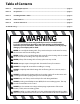
WARNING: Megohmeters apply high voltage and could shock or cause serious injury if improperly used.
Follow megohmeter instructions for safe and proper use.
Please use the Mat/Cable resistance log on next page
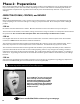
The LoudMouth
™
monitor shown at left
will constantly monitor the heating wire
during the entire installation process. If the
wire is cut or damaged during installation,
this device sounds an alarm. The LoudMouth
will prevent burying a damaged wire below
hardened concrete.