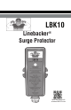
LBK10 Linebacker® Surge Protector Scan for more info at www.LBK10.
LBK10 LINEBACKER® SURGE PROTECTOR INSTALLATION INSTRUCTIONS Surge Protectors are designed to protect equipment from most damaging power surges. While protecting the equipment, the surge protector’s useful life may end and it will need to be replaced. Power surges can be caused by a number of environmental conditions, including lightning, which is the obvious source. No surge protector can provide protection from a direct lightning strike.
WARNING! Risk of Fire or Electric Shock • Completely read these instructions before installing the unit. • Installation and service must be performed by a qualified licensed professional. • Disconnect power at the circuit breaker(s) before installation or service of this device and the equipment it is intended to protect. • All wiring must comply with state and local electrical codes, including the National Electrical Code (NEC) and Canadian Electrical Code (CEC).
NOTE: Some older homes, with older electrical wiring, do not have a ground present. A GOOD GROUND IS IMPERATIVE for the surge protector to properly protect equipment and for safety reasons. If no ground is present, be sure to establish one and confirm that it meets the NEC code. If satisfactory ground cannot be established, do not install the surge protector. CAUTION: Ungrounded power systems are inherently unstable and can produce excessively high line-to-ground voltages during certain fault conditions.
FUNCTIONAL DESCRIPTION When properly installed, this device features internal protection that will disconnect the intended protected equipment from power when the surge protective circuitry is compromised. Use the “Operational Output” to enable activation of the contactor coil circuit and disable power to the equipment when the protector fails. Use the “Alarm Output” connection to activate an external alarm or indicator. External alarm or indicator components are not supplied with this product.
INSTALLATION TIPS: 1. Never sharply bend the surge arrestor wires during termination. 2. Keep the black and white surge arrestor wires as short as possible, and connect the white wire to the best available ground point. This increases the effectiveness and response time of the unit. 3. Always keep the protector at least 3 linear feet (wire length) from the device that is to be protected.
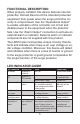
Figure 1A: 208/240VAC Application Figure 1B: 120VAC Application 208/240 Volt Wiring Black to L1 Black to L2 White to Neutral/Ground 120 Volt Wiring Black to L1 Black to L1 White to Neutral/Ground Go to www.LBK10.com for wiring diagrams for other system configurations NOTE: For 120VAC application, connect both black wires to line.
Condensing Unit For an outdoor condensing unit, install the unit on the inside the cabinet area behind the equipment cover. • When installing inside the equipment, be sure to use the external tabs on the surge protector case to secure it to the cabinet case. • Keep the leads as short as possible and make sure there are no 90 degree bends. To install the LBK10 onto the condensing unit: 1. Disconnect power to the condensing unit at the AC disconnect and circuit breaker(s). 2.
Air Handler For an indoor air handler, install the unit through the side of the air handler into the control box where the main power feed enters the air handler. Keep the leads as short as possible and make sure there are no 90 degree bends. To install the unit onto the air handler: 1. Disconnect power to the air handler either at the junction box feeding the air handler or the circuit breaker feeding the air handler. 2.
Furnace For a furnace, install the unit into the control box where the main power feed enters the furnace. Keep the leads as short as possible and make sure there are no 90 degree bends. To install the unit onto a furnace: 1. Disconnect power to the furnace at the AC disconnect, junction box or circuit breaker feeding the furnace. 2. Remove the panel covering the control box where the main power feed enters the furnace. 3.
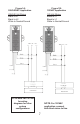
Figure 2A: In this configuration the Alarm Output would only energize when the common has signal from the thermostat. Go to www.LBK10.com for wiring diagrams for other system configurations Figure 2B: In this configuration the Alarm Output will operate even if the thermostat is not trying to run the compressor. Requires another external relay.
SPECIFICATIONS TYPE 2 SPD Voltage: 120/208/240VAC; Single Phase Frequency: 60 Hz Normal Discharge Current (In): 10kA Short Circuit Current Rating (SCCR): 10kA Max. Continuous Operating Voltage (MCOV): L-N 150V Voltage Protection Rating (VPR): L-N/G 600V; L-L 1000V Operating Temperature: -40°F to 158°F (-40°C to 70°C) Type 1 Enclosure Relay Specifications NO/NC Relay Contact Rating: 2A, 24V, AC/DC FOR FURTHER INFORMATION CONTACT TECHNICAL SUPPORT AT 1-800-333-9125 OR GO TO WWW.LBK10.