SUPER ® SUPERSERVER 5010H/5010E SuperServer 5010H SUPER R SUPER R SuperServer 5010E USER’S MANUAL Revision 1.
The information in this User’s Manual has been carefully reviewed and is believed to be accurate. The vendor assumes no responsibility for any inaccuracies that may be contained in this document, makes no commitment to update or to keep current the information in this manual, or to notify any person or organization of the updates. Please Note: For the most up-to-date version of this manual, please see our web site at www.supermicro.com.
Preface Preface About This Manual This manual is written for professional system integrators and PC technicians. It provides information for the installation and use of the SuperServer 5010H/5010E. Installation and maintainance should be performed by experienced technicians only. The SuperServer 5010H/5010E is a high-end single processor 1U rackmount server based on the SC810 1U rackmount server chassis and the Super 370SSR+ (for the 5010H), or the 370SSE+ (for the 5010E) mainboard.
SUPERSERVER 5010H/5010E Manual Chapter 4: System Safety You should thoroughly familiarize yourself with this chapter for a general overview of safety precautions that should be followed when installing and servicing the SuperServer 5010H/5010E. Chapter 5: Advanced Motherboard Setup Chapter 5 provides detailed information on the 370SSR+/370SSE+ motherboard, including the locations and functions of connectors, headers, jumpers, DIP switches and IRQs.
Contacting Supermicro Mainboard Features Setup Running CMOS Setup System Fans C abl es v Motherboard LED IRQs Drive Conn. Jumpers DIP Switches Connectors MB Layout PCI Cards Memory Power Supply Switch I/O Ports Drive Bay Inst.
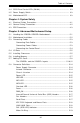
SUPERSERVER 5010H/5010E Manual Table of Contents Preface About This Manual ...................................................................................................... iii Manual Organization ................................................................................................... iii Manual Organization (Flowchart) ............................................................................. v Chapter 1: Introduction to the SuperServer 5010H/5010E 1-1 Overview .......................
Table of Contents Power ........................................................................................................ 3-3 3-4 SCSI Drive Carrier LEDs (5010H) ................................................................ 3-3 3-5 Power Supply Switch .................................................................................... 3-3 3-6 Motherboard LED ............................................................................................
SUPERSERVER 5010H/5010E Manual Wake-On-LAN ........................................................................................ 5-19 5-9 Jumper Settings ............................................................................................. 5-20 Explanation of Jumpers ......................................................................... 5-20 Front Side Bus Speed ........................................................................... 5-20 CMOS Clear ........................................
Table of Contents Event Log Configuration ........................................................................ 7-15 7-5 Chipset Setup ................................................................................................. 7-16 7-6 PCI PnP Setup ................................................................................................ 7-24 7-7 Power Setup .................................................................................................. 7-28 7-8 Boot Setup ........
SUPER SERVER 5010H/5010E User's Manual Notes x
Chapter 1: Introduction Chapter 1 Introduction to the SuperServer 5010H/5010E 1-1 Overview The Supermicro SuperServer 5010H/5010E is a high-end single processor, 1U rackmount server that features some of the most advanced technology currently available. The SuperServer 5010H/5010E is comprised of two main subsystems: the SC810 1U rackmount chassis and the 370SSR+ or 370SSE+ single 370-pin Pentium III FCPGA or Celeron FCPGA/PPGA processor mainboard.
SUPERSERVER 5010H/5010E Manual l One (1) 5V 32-bit, 33 MHz PCI riser card l Rackmount hardware (with screws): Two (2) rack rail assemblies Six (6) brackets for mounting the rack rails to a rack/telco rack l One (1) CD-ROM containing drivers and utilities: Intel's Ô LANDesk Client Manager LAN driver SCSI driver (5010H only) l SuperServer 5010H/5010E User's Manual * Type and number depends upon the configuration ordered.
Chapter 1: Introduction Rear I/O Panel The SC810 is a 1U rackmount chassis. Its I/O panel provides one motherboard expansion slot, one COM port (the other is internal), two USB (External) headers (5010H only), PS/2 mouse and keyboard ports, a graphics port and two Ethernet ports. (See Figure 1-1.) 5010E 5010H Rear of chassis External SCSI (5010H only) Mouse Port Keyboard Port USB Ports COM1 Port VGA (Graphics) Port Ethernet Ports Figure 1-1.
SUPERSERVER 5010H/5010E Manual 1-3 Mainboard Features At the heart of the SuperServer 5010H/5010E lies the 370SSR+/370SSE+, a single processor motherboard designed to provide maximum performance. Below are the main features of the 370SSR+/370SSE+. Chipset Overview Intel’s 815E chipset is made up of three main components: the Graphics and Memory Controller Hub (GMCH), the I/O Controller Hub (ICH) and the Firmware Hub (FWH).
Chapter 1: Introduction Number Generator (RNG) for stronger encryption, digital signing and security protocols. The FWH stores the system BIOS and video BIOS to eliminate a redundant nonvolatile memory component. Processors The 370SSR+/370SSE+ supports single 370-pin Pentium III FCPGA 600 MHz1 GHz and Celeron FCPGA/PPGA 300-700 MHz processors with Front Side Bus Speeds of 133/100/66 MHz. Please refer to the support section of our web site for a complete listing of supported processors (http:// www.
SUPERSERVER 5010H/5010E Manual Onboard Controllers/Ports An onboard IDE controller supports one floppy drive UDMA/100 hard drives or ATAPI devices. Onboard COM port, two USB ports, PS/2 mouse and keyboard ics) port and two LAN (NIC) ports which back each port loses connection.
Chapter 1: Introduction 1-4 CONTACTING SUPERMICRO Headquarters Address: Tel: Fax: E-mail: Web site: Super Micro Computer, Inc. 980 Rock Ave. San Jose, CA 95131 U.S.A. +1 (408) 503-8000 +1 (408) 503-8008 marketing@supermicro.com (General Information) support@supermicro.com (Technical Support) www.supermicro.com European Office Address: Tel: Fax: E-mail: Super Micro Computer B.V. Het Sterrenbeeld 28, 5215 ML, 's-Hertogenbosch, The Netherlands +31 (0) 73-6400390 +31 (0) 73-6416525 sales@supermicro.
SUPERSERVER 5010H/5010E Manual NOTES 1-8
Chapter 2: Server Installation Chapter 2 Server Installation 2-1 Overview This chapter provides a quick setup checklist to get your SuperServer 5010H/5010E up and running. Following these steps in the order given should enable you to have the system operational within a minimum amount of time. This quick setup assumes that your SuperServer 5010H/5010E system has come to you with the processor and memory preinstalled.
SUPERSERVER 5010H/5010E Manual Choosing a Setup Location: - Leave enough clearance in front of the rack to enable you to open the front door completely (~25 inches). - Leave approximately 30 inches of clearance in the back of the rack to allow for sufficient airflow and ease in servicing. ! Warnings and Precautions! ! Rack Precautions: - Ensure that the leveling jacks on the bottom of the rack are fully extended to the floor with the full weight of the rack resting on them.
Chapter 2: Server Installation 2-4 Installing the SuperServer 5010H/5010E into a Rack This section provides information on installing the SuperServer 5010H/5010E into a rack unit. If the 5010H/5010E has already been mounted into a rack, you can skip ahead to Sections 2-5 and 2-6. There are a variety of rack units on the market, which may mean the assembly procedure will differ slightly. The following is a guideline for installing the 5010H/5010E into a rack with the rack rails provided.
SUPERSERVER 5010H/5010E Manual Installing the Chassis Rails: Position the fixed chassis rail sections you just removed along the side of the 5010H/5010E chassis making sure the five screw holes line up. Note that these two rails are left/right specific. Screw the rail securely to the side of the chassis (see Figure 2-2). Repeat this procedure for the other rail on the other side of the chassis. You will also need to attach the rail brackets when installing into a telco rack.
Chapter 2: Server Installation assembly securely to the rack using the brackets provided. Attach the other assembly to the other side of the rack, making sure that both are at the exact same height and with the rail guides facing inward. Installing the Server into the Rack: You should now have rails attached to both the chassis and the rack unit. The next step is to install the server into the chassis. Do this by lining up the rear of the chassis rails with the front of the rack rails.
SUPERSERVER 5010H/5010E Manual Installing the Server into a Telco Rack: If you are installing the SuperServer 5010H/5010E into a Telco type rack, follow the directions given on the previous pages for rack installation. The only difference in the installation procedure will be the positioning of the rack brackets to the rack. They should be spaced apart just enough to accomodate the width of the telco rack. Figure 2-4.
Chapter 2: Server Installation 2-5 Checking the Motherboard Setup After you install the 5010H/5010E in the rack, you will need to open the unit to make sure the motherboard is properly installed and all the connections have been made. 1. Accessing the inside of the 5010H/5010E (see Figure 2-5): First, release the retention screws that secure the unit to the rack. Grasp the two handles on either side and pull the unit straight out until it locks (you will hear a "click").
SUPERSERVER 5010H/5010E Manual Figure 2-5A.
Chapter 2: Server Installation Figure 2-5B.
SUPERSERVER 5010H/5010E Manual 6. Check all cable connections and airflow: Make sure all power and data cables are properly connected and not blocking the airflow. See Section 5-3 for details on cable connections. Also, check the air seals for damage. The air seals are located under the blower fan and beneath the frame cross section that separates the drive bay area from the motherboard area of the chassis. (*Note: Make sure that the air seals are properly installed.
Chapter 2: Server Installation 5. Supplying power to the system: The last thing you must do is to provide input power to the system. Plug the power cord from the power supply unit into a high-quality power strip that offers protection from electrical noise and power surges. It is recommended that you use an uninterruptible power supply (UPS).
SUPERSERVER 5010H/5010E Manual Notes 2-12
Chapter 3: System Interface Chapter 3 System Interface 3-1 Overview There are several LEDs on the control panel as well as others on the SCSI drive carriers and the motherboard to keep you constantly informed of the overall status of the system as well as the activity and health of specific components. There are also two buttons on the chassis control panel and an on/off switch on the power supply. This chapter explains the meanings of all LED indicators and the appropriate response you may need to take.
SUPERSERVER 5010H/5010E Manual 3-3 Control Panel LEDs The control panel located on the front of the SC810 chassis has five LEDs. These LEDs provide you with critical information related to different parts of the system. This section explains what each LED indicates when illuminated and any corrective action you may need to take. l Overheat: Indicates an overheat condition in the chassis. This may be caused by cables obstructing the airflow in the system, or the ambient room temperature being too warm.
Chapter 3: System Interface l Power: Indicates power is being supplied to the system's power supply units. This LED should normally be illuminated when the system is operating. 3-4 SCSI Drive Carrier LEDs (5010H only) Each SCSI drive carrier has two LEDs. l Green: When illuminated, the green LED on the front of the SCSI drive carrier indicates drive activity. A connection to the SCSI SCA backplane enables this LED to blink on and off when that particular drive is being accessed.
SUPERSERVER 5010H/5010E Manual l DA1 (SCSI LED) Indicator (5010H only) There is one SCSI LED Indicator (DA1) on the motherboard. When illuminated, it indicates that SCSI is active. This SCSI LED (DA1) is located near Ultra III LVD Channel A (JA1) on the 370SSR+ mainboard.
Chapter 4: System Safety Chapter 4 System Safety 4-1 Electrical Safety Precautions ! Basic electrical safety precautions should be followed to protect yourself from harm and the SuperServer 5010H/5010E from damage: l Be aware of the locations of the power on/off switch on the chassis as well as the room's emergency power-off switch, disconnection switch or electrical outlet. If an electrical accident occurs, you can then quickly remove power from the system.
SUPERSERVER 5010H/5010E Manual l Motherboard Battery: CAUTION - There is a danger of explosion if the onboard battery (located near the AGP slot) is installed upside down, which will reverse its polarites. This battery must be replaced only with the same or an equivalent type recommended by the manufacturer. Dispose of used batteries according to the manufacturer's instructions.
Chapter 4: System Safety 4-3 ESD Precautions ! Electrostatic discharge (ESD) is generated by two objects with different electrical charges coming into contact with each other. An electrical discharge is created to neutralize this difference, which can damage electronic components and printed circuit boards.
SUPERSERVER 5010H/5010E Manual Notes 4-4
Chapter 5: Advanced Motherboard Setup Chapter 5 Advanced Motherboard Setup This chapter covers the steps required to install the 370SSR+/370SSE+ motherboard into the SC810 chassis, connect the data and power cables and install add-on cards. All motherboard jumpers and connections are also described. A layout and quick reference chart are on pages 5-12 and 5-13. Remember to completely close the chassis when you have finished working with the motherboard to better cool and protect the system.
SUPERSERVER 5010H/5010E Manual static bags when not in use. • For grounding purposes, make sure your computer chassis provides excellent conductivity between the power supply, the case, the mounting fasteners and the motherboard. Unpacking The motherboard is shipped in antistatic packaging to avoid electrical static discharge. When unpacking the board, make sure the person handling it is static protected.
Chapter 5: Advanced Motherboard Setup 5-3 Connecting Cables Now that the motherboard is installed, the next step is to connect the cables to the board. These include the data (ribbon) cables for the peripherals and control panel and the power cables. Connecting Data Cables The ribbon cables used to transfer data from the peripheral devices have been carefully routed to prevent them from blocking the flow of cooling air that moves through the system from front to back.
SUPERSERVER 5010H/5010E Manual Connecting the Control Panel JF1 contains header pins for various front control panel connectors. See Figure 5-1 for the pin locations of the various front control panel buttons and LED indicators. Please note that even and odd numbered pins are on opposite sides. All JF1 wires have been bundled into a single ribbon cable to simplify this connection. Make sure the red wire plugs into pin 1 as marked on the board.
Chapter 5: Advanced Motherboard Setup 5-4 I/O Ports The I/O ports are color coded in conformance with the PC 99 specification. See Figure 5-2 below for the colors and locations of the various I/O ports. Mouse (Green) LAN1 Keyboard (Purple) USB Ports (Black) COM1 Port (Turquoise) LAN2 VGA Graphics Port (Blue) Note: The COM2 Port is a header on the motherboard, located behind the mouse/keyboard ports. Figure 5-2.
SUPERSERVER 5010H/5010E Manual 2. Attaching heat sinks to the processors: One passive heat sink has been included with your SuperServer 5010H/ 5010E. Secure the heat sink to the processor with a suitable thermal compound to best conduct the heat from the processor to the heat sink. Make sure that you apply the compound evenly on the CPU's die, and that good contact is made between the CPU chip (the die) and the heat sink.
Chapter 5: Advanced Motherboard Setup 5-6 Installing Memory CAUTION! Exercise extreme care when installing or removing DIMM modules to prevent any possible damage. The MEC must be populated in the manner described in Step 2 below. ! 1. Memory support: The 370SSR+/SSE+ supports 64MB/128MB/256MB/512 MB unbuffered SDRAM in three 25-degree DIMMs. PC133 and PC100 memory are both supported at their respective speeds.
SUPERSERVER 5010H/5010E Manual 5-7 Adding PCI Cards 1. 32-bit PCI slot: The 370SSR+/370SSE+ has one 32-bit MHz 5V PCI slot available. A riser card designed specifically for using this slot in a 1U rackmount chassis is included with your system. This riser card allows an installed PCI card to sit at a 90 degree angle so it can fit inside the chassis. This riser card accommodates 32-bit, 33 MHz 5V PCI cards. Figure 5-5 shows the riser card. 2.
Chapter 5: Advanced Motherboard Setup Figure 5-5. 5V, 32-bit 33 MHz Riser Card PCI Riser Card CPU Socket 370SSR+ Motherboard Memory Modules 5010H PCI Riser Card CPU Socket Memory Modules 370SSE+ Motherboard Figure 5-6.
SUPERSERVER 5010H/5010E Manual Figure 5-7A. Super 370SSR+ Layout (not drawn to scale) COM2 1 JP12 J30 KB/ MOUSE JPWAKE ATX POWER 1 CPU FAN 1 JP11 8.6" 1 J1 J2 J3 J29 J32, J33 USB 370 FCPGA/PPGA 1 IR COM1 DIMM2 J4 VGA DIMM1 DIMM0 Processor 1PW LED JF1 GMCH LAN1 1 J18 J43 J51 J26 4xAGP USB2 USB3 PCI 1 ICH2 J38 IDE2 1 J37 FLOPPY SUPER ® JP35 PCI 2 JP31 J39 BIOS FWH JP34 1 IDE1 Ultra160 SCSI CH A PCI 4 JA3 Ultra160 SCSI CH B JA2 Ext.
Chapter 5: Advanced Motherboard Setup 370SSR+ Quick Reference (for 5010H) Jumpers JBT1 JP11/12 JP31 JP32 JP35 JPA1 JPA2 JPWAKE Description CMOS Clear Front Side Bus Speed LAN2 Enable/Disable Speaker En/Disable LAN1 Enable/Disable SCSI Ch A Termination SCSI Ch B Termination Keyboard Wake-Up Connectors COM1/COM2 CPU/CH/OH FAN J1, J2, J3 JA1 JA2 JA3 J18, J19 JP26 J29 J30 J32, J33, J43, J51 JF1 JL1 JOH JWOR LAN1/LAN2 VGA WOL Default Setting Pins 1-2 (Normal) Both: Pins 1-2 (Auto) Closed (Enabled) Closed (E
SUPERSERVER 5010H/5010E Manual Figure 5-7B. Super 370SSE+ Layout (not drawn to scale) COM2 CPU FAN JP12 1 ATX POWER 1 J1 J2 J3 J29 J32, J33 USB JF1 1 IR 370 FCPGA/PPGA COM1 1 PW LED J30 KB/ MOUSE JPWAKE 1 JP11 8.
Chapter 5: Advanced Motherboard Setup 370SSE+ Quick Reference (5010E only) Jumpers JP11/12 JP31 JP32 JP33 JPWAKE Description Front Side Bus Speed LAN2 Enable/Disable Speaker En/Disable LAN1 Enable/Disable Keyboard Wake-Up Connectors COM1/COM2 CPU/CH/OH FAN J1, J2, J3 J18, J19 JP26 J29 J30 J32, J33,J43,J51 JF1 JL1 JOH JWOR LAN1/LAN2 VGA WOL Default Setting Both: Pins 1-2 (Auto) Closed (Enabled) Closed (Enabled) Pins 1-2 (Enabled) Pins 1-2 (Disabled) Description COM1/COM2 Serial Port Connector CPU/Chass
SUPERSERVER 5010H/5010E Manual 5-8 Connector Definitions Power Supply Connector ATX Power Supply 20-pin Connector Pin Definitions The primary power supply connector on the 370SSR+/370SSE+ is designated as ATX POWER. This is a 20-pin connector. Attach an ATX power supply cable to J29 by aligning the tab on the connector. (Refer to the table on the right for pin definitions.) Pin Number 1 2 3 4 5 6 7 8 9 10 Definition Pin Number Definition +3.3V 11 3.3V +3.
Chapter 5: Advanced Motherboard Setup Power LED The Power LED connection is located on pins 15 and 16 of JF1. When illuminated, this LED indicates that power is applied to the system. There is also a 3-pin header for the Power LED located at J50. See the tables on the right for pin definitions and Figure 5-1 for pin locations.
SUPERSERVER 5010H/5010E Manual Overheat LED (JOH) Pins 7 and 8 of JF1 are for the Overheat LED, which provides you with advanced warning of chassis overheating. This LED will also illuminate if the blower fan fails, which will cause the chassis temperature to rise. Refer to the table on the right for pin definitions and Figure 5-1 for pin locations. Overheat LED Pin Definitions (JF1) Pin N u m b e r Definition 7 Power Control 8 Reset The Reset connection is located on pins 3 and 4 of JF1.
Chapter 5: Advanced Motherboard Setup Universal Serial Bus (USB) Two External Universal Serial Bus connectors (USB0 and USB1) are located on J32, J33, and two Internal USB headers (USB2, USB3) are located on J43, J51. Refer to the tables on the right for pin definitions.
SUPERSERVER 5010H/5010E Manual ATX PS/2 Keyboard and PS/2 Mouse Ports The ATX PS/2 keyboard and the PS/2 mouse are located on J30. See the table on the right for pin definitions. (The mouse port is above the keyboard port. See Figure 5-8.) PS/2 Keyboard and Mouse Port Pin Definitions (J30) Pin Number Definition Data 1 NC 2 Ground 3 VCC 4 Clock 5 NC 6 LAN1/LAN2 Ports Two Ethernet ports (designated LAN1 and LAN2) are located beside the VGA port on the I/O backplane. These ports accept RJ45 type cables.
Chapter 5: Advanced Motherboard Setup Wake-On-Ring The Wake-on-Ring (JWOR) header allows your computer to receive and be "woken up" by an incoming call when in the suspend state. Refer to the table on the right for pin definitions. The 370SSR+/ 370SSE+ meets the PCI 2.2 standard, which provides the PME function to support WOR and WOL. You must also have a WOR card and cable to use WOR.
SUPERSERVER 5010H/5010E Manual 5-9 Jumper Settings Explanation of Jumpers Connector Pins To modify the operation of the motherboard, jumpers can be used to choose between optional settings. Jumpers create shorts between two pins to change the function of the connector. Pin 1 is identified with a square solder pad on the printed circuit board. See the motherboard layout pages for jumper locations.
Chapter 5: Advanced Motherboard Setup CMOS Clear CMOS Clear Jumper Settings (JBT1) Refer to the table on the right for setting JBT1 to clear CMOS. Always remove the AC power cord from the system before clearing CMOS. Jumper Position 1-2 2-3 Definition Normal CMOS Clear Speaker Enable/Disable Jumper JP32 allows you to enable or disable the onboard speaker. Refer to the table on the right for jumper settings. Onboard LAN Enable/ Disable SSE+ (Rev. 1.1, Rev. 1.11):JP31, JP33 SSR+/SSE+ (Rev.1.
SUPERSERVER 5010H/5010E Manual LVD Channel A SCSI Termination Enable/Disable (5010H only) Jumper JPA1 allows you to enable or disable termination for the LVD Channel A SCSI connector. The normal (default) position is open to enable SCSI termination. See the table on the right for jumper settings. LVD Channel B SCSI Termination Enable/Disable (5010H only) Jumper JPA2 allows you to enable or disable termination for the LVD Channel B SCSI connector.
Chapter 5: Advanced Motherboard Setup 5-10 Floppy/Hard Disk and SCSI Connections Be aware of the following when connecting the floppy and hard disk drive cables: • A red mark on a wire typically designates the location of pin 1. • A single floppy disk drive ribbon cable has 34 wires and two connectors to provide for two floppy disk drives. The connector with the twisted wires always connects to drive A, and the connector that does not have twisted wires always connects to drive B.
SUPERSERVER 5010H/5010E Manual Ultra160 SCSI Connectors Refer to the table below for pin definitions for the Ultra160 SCSI connectors located at JA1, JA2 and JA3.
Chapter 6: Advanced Chassis Setup Chapter 6 Advanced Chassis Setup This chapter covers the steps required to install components and perform maintenance on the SC810 chassis. For component installation, follow the steps in the order given to eliminate the most common problems encountered. If some steps are unnecessary, skip ahead to the step that follows. Tools Required The only tool you will need to install components and perform maintainance is a Philips screwdriver.
SUPERSERVER 5010H/5010E Manual 5010E IDE Drives Screws (3 on each side) Rack Unit Retention SUPER Slim CD-ROM Drive Floppy Drive SUPER R Control Panel/ System LEDs System Reset Main Power R SCSI Drives 5010H Figure 6-1. Chassis Front Views 5010E PCI Card Release Latch PCI Slot External SCSI Connector 5010H Figure 6-2.
Chapter 6: Advanced Chassis Setup 6-3 System Fans One 10-cm blower fan provides all the cooling needed for the SuperServer 5010H/5010E. An optional 4-cm fan can also be installed into the chassis cross section just above the ribbon cable to the JA1 SCSI connector on the motherboard. The chassis includes air seals under the blower fan and at the chassis cross section, which separates the drive bay area from the motherboard area of the chassis to promote better airflow.
SUPERSERVER 5010H/5010E Manual Fan Mounting Posts Optional Fan Location Chassis Cross Section Blower Fan Figure 6-3. 6-4 System Cooling Fans Drive Bay Installation/Removal Accessing the Drive Bays SCSI Drives: You do not need to access the inside of the chassis to replace or swap SCSI drives. Proceed to the next step for instructions. Note: You must use standard 1" high, 80-pin SCA SCSI drives in the SuperServer 5010H.
Chapter 6: Advanced Chassis Setup SCSI Drive Installation (5010H only) 1. Mounting a SCSI drive in a drive carrier: The SCSI drives are mounted in drive carriers to simplify their installation and removal from the chassis. These carriers also help promote proper airflow for the SCSI drive bays. For this reason, even empty carriers without SCSI drives installed must remain in the chassis.
SUPERSERVER 5010H/5010E Manual 2. Installing/removing hot-swap SCSI drives: Two SCSI drive bays are located in the front of the chassis, making them easily accesible for installation and removal. These SCSI drives are hotswap units, meaning they can be installed and removed without powering down the system. To remove, first push the release button located beside the drive LEDs, then swing the burgundy colored handle fully out and use it to pull the unit straight out (see Figure 6-5).
Chapter 6: Advanced Chassis Setup SCSI Power Cables SCSI power cables should be routed so that they do not block the airflow through the chassis. There is a 4-pin connector for the power cables. SCA Backplane The SCSI drives plug into an SCA backplane that provides power, SCSI ID and bus termination. A RAID controller can be used with the SCA backplane to provide data security. The operating system you use must have RAID support to enable the hot-swap capability of the SCSI drives.
SUPERSERVER 5010H/5010E Manual 6-5 Power Supply The SuperServer 5010H/5010E has a single 200 watt power supply. This power supply has an auto-switching capability, which enables it to automatically sense and operate with either 110 or 220 volt inputs. A power on/off switch is located at the back of the power supply. Turning this power switch to the off position will remove both main and standby power from the system.
Chapter 6: Advanced Chassis Setup Figure 6-6. Chassis Rear View 5010E Power Supply I/O Ports (see Figure 1.
SUPERSERVER 5010H/5010E Manual Notes 6-10
Chapter 7: AMIBIOS Chapter 4 BIOS 7-1 Introduction This chapter describes the AMIBIOS for the 5010H/5010E. The AMI ROM BIOS is stored in a Flash EEPROM and can be easily upgraded using a floppy disk-based program. Note: Due to periodic changes to BIOS, some settings may have been added or deleted and might not yet be recorded in this manual. Refer to the Manual Download area of our web site for any changes to BIOS that are not reflected in this manual.
SUPERSERVER 5010H/5010E User's Manual 7-2 BIOS Features • Supports Plug and Play V1.0A and DMI 2.3 • Supports Intel PCI (Peripheral Component Interconnect) (PME) local bus specification • Supports Advanced Power Management (APM) specification v 1.1 • Supports ACPI • Supports Flash ROM AMIBIOS supports the LS120 drive made by Matsushita-Kotobuki Electronics Industries Ltd.
Chapter 7: AMIBIOS The Main BIOS Setup Menu Press the key during the POST (Power On Self Test) to enter the Main Menu of the BIOS Setup Utility. All Main Setup options are described in this section. The Main BIOS Setup screeen is displayed below. BIOS SETUP UTILITY Main Advanced Chipset PCIPnP Power Boot Security Exit : : : 07.
SUPERSERVER 5010H/5010E User's Manual 7-4 Advanced Chipset Setup Choose Advanced BIOS Setup from the AMIBIOS Setup Utility main menu with the Left/Right arrow keys. You should see the following display. Select one of the items in the left frame of the screen, such as SuperIO Configuration, to go to the sub screen for that item. Advanced BIOS Setup options are displayed by highlighting the option using the arrow keys. All Advanced BIOS Setup options are described in this section.
Chapter 7: AMIBIOS CPU Overheat Warning This option allows you to Enable or Disable a system overheat warning signal, used to notify you in the event of a dangerous rise in heat levels. CPU Overheat Warning This option allows you to specify the temperature threshold that, when exceeded, will trigger the overheat warning alarm. BIOS The rest of the Health Monitor menu lists various voltages and temperatures as they are currently being measured.
SUPERSERVER 5010H/5010E User's Manual Super IO Configuration After selecting the settings for "Health Monitor Features",use the Up/Down arrow keys to select the "SuperIO Configuration" line. When the "SuperIO Configuration" line is highlighted, hit "ENTER" to display its menu.
Chapter 7: AMIBIOS Serial Port2 Mode This option specifies Serial Port2 Mode. The settings for this item include Normal, IRDA1.6ms, IRDA311.6, ASKIR, ASKIR500, ASKIRDem, ASKIRD500. Parallel Port Address This option specifies the I/O address used by the parallel port. The settings for this item include Disabled, 378, 278 and 3BC. Select your setting and then press "Enter". Parallel Port Mode This option specifies the parallel port mode.
SUPERSERVER 5010H/5010E User's Manual Power Loss Control This option determines how the system will react when power is reapplied after being lost unexpectedly.
Chapter 7: AMIBIOS Type This option sets the type of device that the AMIBIOS attempts to boot from after AMIBIOS POST is completed. The settings include Not installed, Auto, CDROM and ARMD. The "Auto" setting allows BIOS to automatically detect the presence of the IDE controller. LBA/Large Mode LBA (Logical Block Addressing) is a method of addressing data on a disk drive. In LBA mode, the maximum drive capac ity is 137 GB. The settings are Disabled and Auto. Select "Disabled" to disable LBA mode.
SUPERSERVER 5010H/5010E User's Manual tect the DMA Mode. Select SWDMA0 through SWDMA2 to set single word DMA0 through DMA2. Select MWDMA0 through MWDMA2 to set Multi-word DMA0 through DMA2. Select UDMA0 trhough UDMA4 to set Ultra DMA0 through Ultra DMA4. S.M.A.R.T. S.M.A.R.T stands for Self-Monitoring Analysis and Reporting Technology, a feature that can help predict impending drive failures. The settings are Auto, Disabled and Enabled. Select "Enabled" or "Disabled" to enable or disable the S.M.A.R.T.
Chapter 7: AMIBIOS Hard Disk Write Protect This item allows the user to prevent the hard disk from being overwritten. The options are Enabled or Disabled. Enabled allows the drive to be used normally; read, write and erase functions can all be performed. Disabled prevents the hard disk from being erased. This function is effective only when the device can be accessed through BIOS. ATA(PI) Detect Timeout Set this option to stop the system search for ATAPI devices within the specified number of seconds.
SUPERSERVER 5010H/5010E User's Manual Boot Settings Configuration Quick Boot This option allows the BIOS to skip certain tests that are normally performed on boot up. You can disable the option to speed up boot time. The settings are Disabled and Enabled. Quiet Boot If Disabled, this option will cause the normal POST messages to be displayed upon setup. When Enabled, the OEM logo is displayed instead of the POST messages.
Chapter 7: AMIBIOS System Keyboard This option is to let the system know if a keyboard is Present or Absent. Primary Display This option specifies the type of monitor display you have installed on the system. The settings are Absent, VGA/EGA, Color 40 x 25, Color 80 x 25 and monochrome. Parity Check Use this option to either Enable or Disable the use of memory parity checking. Boot to OS/2 This option can be used to boot the system to an OS/2 operating system. The settings are No and Yes.
SUPERSERVER 5010H/5010E User's Manual be used to slow the computer system down or to troubleshoot error messages. Write-Thru: This option allows the computer system to use the internal CPU L1 cache as Write-Through cache. Write-Through cache is slower than Write-Back cache. It performs write operations to the internal L1 CPU cache and system memory simultaneously.Write-Back This option allows the computer system to use the internal CPU L1 cache as Write-Back cache.
Chapter 7: AMIBIOS Event Log Configuration Event Logging This option Enables or Disables the logging of events. You can use this screen to select options for the Event Log Configuration Settings. You can access sub screens to view the event log and mark all events as read. Use the up and down arrow keys to select an item, and the plus (+) and minus (-) keys to change the option setting. The settings are described on the following pages. The screen is shown below.
SUPERSERVER 5010H/5010E User's Manual 7-5 Chipset Setup Choose Chipset Setup from the AMIBIOS Setup Utility main menu. The screen is shown below. All Chipset Setup options are described following the screen. You can use this screen to select options for the GHCH Configuration.
Chapter 7: AMIBIOS Internal Graphics Mode Select This option selects the mode for the internal graphics mode. Settings in- clude Disabled, Enabled; 512 KB and Enabled; 1 MB. Enabled; 1MB: This option allows the Internal Graphic controller to allocate 1 MB of system memory for video display use. Enabled; 512KB: This option allows the Internal Graphic controller to allocate 512 KB of system memory for video display use. Disabled: This option allocates no system memory for video display use.
SUPERSERVER 5010H/5010E User's Manual Init Display Cache Memory This option allows the Initial Display cache memory to be adjusted. The setting are Enabled and Disabled. Paging Mode Control This option allows the paging mode controls to be adjusted to either Close or Open. RAS-to-CAS Latency Override The RAS-to-CAS Override is adjusted with this option. The settings are Disabled and Enabled. Disabled: This option allows RAS-to-CAS. Enabled: This option overrides RAS-to-CAS.
Chapter 7: AMIBIOS System Memory Frequency This option allows the system memory frequency to be adjusted. The settings are 100 MHz (for PC100 memory), 133 MHz (for PC133 memory) and Auto, which allows the system memory frequency to auto select itself SDRAM Refresh This option sets the refresh rate for the system memory. Auto, 15.6 mS, 7.8 mS and 128 CLKS. Settings include DRAM Cycle Time (SCLKS) This option allows you set the DRAM cycle time to 5/7, 6/8 or Auto.
SUPERSERVER 5010H/5010E User's Manual DRAM Page Closing Policy The settings for this option are Close and Open. Memory Hole Some ISA cards may require specific areas of memory to function. This can be done by choosing the 15 MB - 16 MB option to reserve the area. The settings for this option are Disabled and 15 MB-16 MB. ICH2 Configuration You can use this screen to select options for the ICH2 Configuration.
Chapter 7: AMIBIOS SMBus Controller The settings for this option are Enabled and Disabled. LPC 4Eh-4Fh Decode This option allows the LPC 4Eh-4Fh to be set. and Enabled. The settings are Disabled DMA-0 Type DMA-1 Type DMA-2 Type DMA-3 Type DMA-4 Type DMA-5 Type DMA-6 Type This above options allow you to change the protocol for DMA-0 through DMA-7. The settings for all are PC/PCI and LPC DMA.
SUPERSERVER 5010H/5010E User's Manual Processor Serial Number Intel includes a serial number in their processors to act as a unique system identifier. For privacy reasons, you can disable the release of this identifier. The settings for this option are Disabled and Enabled. Disabled: This setting restricts all access to the CPU serial number from your CPU. Enabled: This setting allows the operating system and applications to be able to read the CPU serial number from your CPUs.
Chapter 7: AMIBIOS C000, 16k Shadow C400, 16k Shadow C800, 16k Shadow CC00, 16k Shadow D000, 16k Shadow D400, 16k Shadow D800, 16k Shadow These options specify how the 16 KB of video ROM at each of the above addresses is treated. The settings are Disabled, Enabled, and Cached/WP . When Disabled, the contents of the video ROM are not copied to RAM. When Enabled, the contents of 16 KB of video ROM beginning at the above address are copied (shadowed) from ROM to RAM for faster application.
SUPERSERVER 5010H/5010E User's Manual 7-6 PCI PnP Setup Choose PCI/PnP Setup from the AMIBIOS Setup main menu. All PCI/PnP options are described in this section. The PCI/PnP Setup screen is shown below.
Chapter 7: AMIBIOS PCI Latency Timer This option specifies the latency timing of the PCI clocks for all PCI devices. Settings include 32, 64, 96, 128, 160, 192, 224 and 248 PCI clocks. Allocate IRQ to PCI VGA This option lets you allocate an interrupt request (IRQ) to the PCI VGA adapter card (if used). The settings are Yes and No. Palette Snooping When enabled, this option informs PCI devices that an ISA graphics device is installed. The settings are Disabled and Enabled.
SUPERSERVER 5010H/5010E User's Manual Legacy USB Support This option allows Legacy USB support. The settings are Disabled, En- abled and Auto. Disabled prevents the use of any USB device in DOS or during system boot. Enabled allows the use of USB devices during boot and while using DOS. The Auto setting auto detects USB keyboards or mice and if found, allows them to be utilized during boot and while using DOS.
Chapter 7: AMIBIOS DMA Channel 0 DMA Channel 1 DMA Channel 3 DMA Channel 5 DMA Channel 6 DMA Channel 7 Each of the above list of DMA channel setting options can be set to Available and Reserved. Available means the specified DMA channel is available for use by PCI/PnP devices. Reserved means the specified DMA channel is reserved for use by Legacy ISA devices. Reserved Memory Size BIOS This option specifies the size of a memory area to be reserved for Legacy ISA adapter cards.
SUPERSERVER 5010H/5010E User's Manual 7-7 Power Setup Choose Power Setup from the AMIBIOS Setup main menu. All Power Setup options are described in this section. The Power Setup screen is shown below.
Chapter 7: AMIBIOS ACPI Aware O/S This option allows the system to utilize Intel's ACPI (Advanced Configuration and Power Interface) specification. Settings are No and Yes. DOS®, Windows 3.x®, Windows 95 and Windows NT® are examples of non-ACPI aware operating systems. Windows 98®, Windows ME, and Windows 2000® are examples of ACPI aware operating systems. This allows you to enable or disable the Suspend to RAM feature. Settings are Disabled and Enabled.
SUPERSERVER 5010H/5010E User's Manual Suspend Power Saving Type The settings for this option are C2 and S1. The C2 setting allows the CPU (microprocessor) to be put in a low power state. In this state, incoming interrupts wake-up the CPU (microprocessor) to process them (I/O APIC). S1 allows the system to enter the S1 POS (Power On Suspend) state.
Chapter 7: AMIBIOS Green PC Monitor Power State This option specifies the power state that a green PC-compliant monitor enters when BIOS places it in a power saving state after the specified period of display inactivity has expired. The settings include Standby, Suspend and Off. Video Power Down Mode This option specifies the power state that the VGA video subsystem enters after the specified period of display inactivity has expired. The settings include Disabled, Standby and Suspend.
SUPERSERVER 5010H/5010E User's Manual THRM Throttle Ratio THRM throttling is used to lower power consumption and reduce heat. The settings include 87.5%, 75.0%, 62.5%, 50%, 37.5%, 25% and 12.5%. Intruder Sel This option allows you to set the Intruder SEL setting to SCI or SMI. SCI stands for System Control Interrupt. This is considered to be ACPI (Advanced Configuration and Power Interface) mode.
Chapter 7: AMIBIOS TCO Logic SMI Enable This allows the system to generate a System Management Interrupt when a century rollover occurs. The settings for this option Disabled and Enabled. RTC Resume This allows you to direct the system to resume operation at a predetermined time by using the real-time clock. The settings for this option Disabled and Enabled. RTC Alarm Date This allows you to input the date you want the system to resume operation according to a real-time clock wake-up.
SUPERSERVER 5010H/5010E User's Manual SMBUS Resume This allows you to wake up the system from a System Management Bus device. The settings for this option Disabled and Enabled. LAN Wake-Up This allows you to wake up LAN1 and LAN2 from a System Management Bus device. The settings for this option Disabled and Enabled. 7-8 Boot Setup Choose Boot Setup from the AMIBIOS Setup main menu. All Boot Setup options are described in this section. The Boot Setup screen is shown below.
Chapter 7: AMIBIOS 2nd Boot Device The settings for the 2nd Boot Device are Removeable Device, Hard Drive, ATAPI CDROM, Onboard LAN1Option and Onboard LAN2 Option. 3rd Boot Device The settings for the 3rd Boot Device are Removeable Device, Hard Drive, ATAPI CDROM, Onboard LAN1Option and Onboard LAN2 Option. Hard Disk Drives Use this screen to view the hard drives that have been auto-detected or entered manually on your system.
SUPERSERVER 5010H/5010E User's Manual 7-9 Security Setup Choose Security Setup from the AMIBIOS Setup main menu. All Security Setup options are described in this section. The Security Setup screen is shown below. BIOS SETUP UTILITY Main Advanced Supervisor Password User Password Chipset : : > Change Supervisor Password > Change User Password > Clear User Password Boot Sector Virus Protection PCIPnP Power Not Installed Not Installed Boot Security Exit Install or Change the password.
Chapter 7: AMIBIOS Change Supervisor Password This option allows you to change a supervisor password that was entered previously. Change User Password This option allows you to change a user password that was entered previously. Clear User Password Use this option to clear the user password so that it is not required to be entered when the system boots up.
SUPERSERVER 5010H/5010E User's Manual 7-10 Exit Setup Choose Exit Setup from the AMIBIOS Setup main menu. All Exit Setup options are described in this section. The Exit Setup screen is shown below. BIOS SETUP UTILITY Main > > > > > Advanced Chipset PCIPnP Power Boot Security Exit Exit system setup with saving the changes.
Chapter 7: AMIBIOS Load Optimal Defaults Highlighting this setting and then pressing provides the optimum performance settings for all devices and system features. Load Failsafe Defaults Highlighting this setting and then pressing provides the safest set of parameters for the system. Use them if the system is behaving erratically.
SUPERSERVER 5010H/5010E User's Manual Notes BIOS 7-40
Appendix A: BIOS Error Beep Codes Appendix A BIOS Error Beep Codes & Messages During the POST (Power-On Self-Test) routines, which are performed each time the system is powered on, errors may occur. Non-fatal errors are those which, in most cases, allow the system to continue the boot-up process. The error messages normally appear on the screen. Fatal errors are those which will not allow the system to continue the boot-up procedure.
SUPERSERVER 5010H/5010E Manual AMI BIOS Error Beep Codes Beep Code 1 beep Error Message BIOS ROM file absent 3 beeps Base 64KB memory failure Flash program successful 5 beeps Media read error 6 beeps Keyboard controller Gate A20 failure Processor exception interrupt error Display memory read/write error 7 beeps 8 beeps 10 beeps Flash erase error 11 beeps Flash program error BIOS ROM file incorrect size 12 beeps The memory refresh circuitry on the motherboard is faulty The BIOS was unable to
Appendix B: AMIBIOS POST Checkpoint Codes Appendix B AMIBIOS POST Checkpoint Codes When AMIBIOS performs the Power On Self Test, it writes diagnostic codes checkpoint codes to I/O port 0080h. If the computer cannot complete the boot process, diagnostic equipment can be attached to the computer to read I/O port 0080h.
SUPERSERVER 5010H/5010E Manual B-2 Bootblock Recovery Codes The bootblock recovery checkpoint codes are listed in order of execution: Checkpoint Code Description E0h The onboard floppy controller if available is initialized. Next, beginning the base 512 KB memory test. E1h Initializing the interrupt vector table next. E2h Initializing the DMA and Interrupt controllers next. E6h Enabling the floppy drive controller and Timer IRQs. Enabling internal cache memory. Edh Initializing the floppy drive.
Appendix B: AMIBIOS POST Checkpoint Codes B-3 Uncompressed Initialization Codes The following runtime checkpoint codes are listed in order of execution. These codes are uncompressed in F0000h shadow RAM. Checkpoint Code Description 03h The NMI is disabled. Next, checking for a soft reset or a power on condition. 05h The BIOS stack has been built. Next, disabling cache memory. 06h Uncompressing the POST code next. 07h Next, initializing the CPU and the CPU data area.
SUPERSERVER 5010H/5010E Manual Checkpoint Code Description 25h Interrupt vector initialization is done. Clearing the password if the POST DIAG switch is on. 27h Any initialization before setting video mode will be done next. 28h Initialization before setting the video mode is complete. Configuring the monochrome mode and color mode settings next. 2Ah Bus initialization system, static, output devices will be done next, if present. See the last page for additional information.
Appendix B: AMIBIOS POST Checkpoint Codes Checkpoint Code Description 4Bh The amount of memory above 1 MB has been found and verified. Checking for a soft reset and clearing the memory below 1 MB for the soft reset next. If this is a power on situation, going to checkpoint 4Eh next. 4Ch The memory below 1 MB has been cleared via a soft reset. Clearing the memory above 1 MB next. 4Dh The memory above 1 MB has been cleared via a soft reset. Saving the memory size next. Going to checkpoint 52h next.
SUPERSERVER 5010H/5010E Manual Checkpoint Code Description 60h The DMA page register test passed. Performing the DMA Controller 1 base register test next. 62h The DMA controller 1 base register test passed. Performing the DMA controller 2 base register test next. 65h The DMA controller 2 base register test passed. Programming DMA controllers 1 and 2 next. 66h Completed programming DMA controllers 1 and 2. Initializing the 8259 interrupt controller next.
Appendix B: AMIBIOS POST Checkpoint Codes Checkpoint Code Description 89h The programming after WINBIOS Setup has completed. Displaying the power on screen message next. 8Bh The first screen message has been displayed. The message is displayed. Performing the PS/2 mouse check and extended BIOS data area allocation check next. 8Ch Programming the WINBIOS Setup options next. 8Dh The WINBIOS Setup options are programmed. Resetting the hard disk controller next.
SUPERSERVER 5010H/5010E Manual Checkpoint Code Description 9Bh Returned after setting the RS-232 base address. Performing any required initialization before the Coprocessor test next. 9Ch Required initialization before the Coprocessor test is over. Initializing the Coprocessor next. 9Dh Coprocessor initialized. Performing any required initialization after the Coprocessor test next. 9Eh Initialization after the Coprocessor test is complete. Checking the extended keyboard, keyboard ID, and Num Lock key next.
Appendix B: AMIBIOS POST Checkpoint Codes B-4 Bus Checkpoint Codes The system BIOS passes control to different buses at the following checkpoints: Checkpoint Code Description 2Ah Initializing the different bus system, static, and output devices, if present. 38h Initialized bus input, IPL, and general devices, if present. 39h Displaying bus initialization error messages, if any. 95h Initializing bus adaptor ROMs from C8000h through D8000h.
SUPERSERVER 5010H/5010E Manual Notes B-10
Appendix C: List of Figures Appendix C List of Figures Description Page I/O Shield 1-3 Identifying the Sections of the Rack Rails 2-3 Installing Chassis Rails 2-4 Installing the Server into a Rack 2-5 Installing the Server into a Telco Rack 2-6 Accessing the Inside of the SuperServer 5010 2-8,9 Control Panel Header Pins 5-4 I/O Ports 5-5 FCPGA Socket: Empty and with Processor Installed 5-6 Heat Sink Installation Procedures 5-6 Side View of DIMM Installation into Slot 5-7 3.
SUPERSERVER 5010H/5010E Manual Notes C-2
Appendix D: System Specifications Appendix D System Specifications Processors One 370-pin Intel Pentium III FCPGA 600 MHz - 1 GHz or a Celeron FCPGA/PPGA 300-700 MHz CPU with a 133 or 100 MHz FSB Memory Capacity 3 DIMM slots to support a maximum of 512 MB SDRAM DIMM Sizes 128 MB / 256 MB / 512 MB SDRAM modules supported SCSI Controller (5010H only) Adaptec AIC-7899 for dual channel Ultra160 SCSI SCSI Backplane Controller (5010H only) QLogic GEM354 controller for SAF-TE compliant SCA backplane SCSI Dri
SUPERSERVER 5010H/5010E Manual PCI Expansion Slot One (1) onboard 32-bit 33 MHz (5V) PCI slot (*Default-- bundled with a 32-bit 33 MHz 5V Riser Card) Power Supply Type: 1 x 200W with +3.3V, +5V, +12V, -5V and -12V main DC outputs and a 5V standby output.