
User's Manual

Chapter 2: Installation
2-13
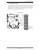
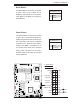
Power Button
OH/Fan Fail LED
1
NIC1 LED
Reset Button
2
HDD LED
Power LED
Reset
PWR
Vcc
Vcc
Vcc
Vcc
Ground
Ground
1920
Vcc
X
Ground
NMI
X
Vcc
PWR Fail LED
NIC2 LED
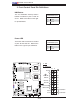
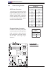
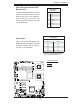
Power Button
The Power Button connection is located
on pins 1 and 2 of JF1. Momentarily con-
tacting both pins will power on/off the sys-
tem. This button can also be confi gured
to function as a suspend button (with a
setting in the BIOS - see Chapter 4). To
turn off the power when set to suspend
mode, press the button for at least 4
seconds. Refer to the table on the right
for pin defi nitions.
Power Button
Pin Defi nitions (JF1)
Pin# Defi nition
1 Signal
2 +3V Standby
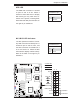
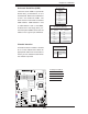
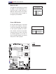
Reset Button
The Reset Button connection is located
on pins 3 and 4 of JF1. Attach it to a
hardware reset switch on the computer
case. Refer to the table on the right for
pin defi nitions.
Reset Button
Pin Defi nitions (JF1)
Pin# Defi nition
3 Reset
4 Ground
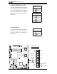
A. Reset Button
B. PWR Button
A
B
JBT
JWOL1
JPL1
JWD
JPG1
JI2C2
JI2C4
JI2C1
JI2C3
J8
JPT1
SPKR
JD1
J18
JP2
JOH1
JL1
JP1
J7
FAN6
FAN5
FAN1
FAN2
FAN3
FAN4
LED5
LED6
LE1
USB6
T-SGPIO 2
USB4/5
USB2/3
COM2
LAN2
LAN1
PWR
BANK1
COM1
VGA
USB0/1
BANK2
KB/MS
DIMM1A
DIMM1B
DIMM2A
DIMM2B
CPU2
CPU1
Slot5 PCI-E x8
Slot6 PCI-E x8
Slot7 SIMLP
Slot4 PCI-E x8
Slot1 PCI-X 133MHz
Slot 2 PCI-E x4
Slot 0 PCI-U
I-SATA5
I-SATA4
FLOPPY
I-SATA0
I-SATA2
I-SATA1
I-SATA3
X7DWE
IDE#1
SMB
FP CTRL
JPL2
Super I/O
LAN
CTRL
Intel 5400
North Bridge
Slot3 PCI-E x8
Intel ESB2
South Bridge
BIOS
T-SGPIO1
VGA
CTRL
24-Pin ATX PWR
8-Pin PWR