
User's Manual

Chapter 2: Installation
2-15
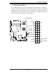
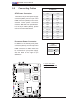
JBT
JWOL1
JPL1
JWD
JPG1
JI2C2
JI2C4
JI2C1
JI2C3
J8
JPT1
SPKR
JD1
J18
JP2
JOH1
JL1
JP1
J7
FAN6
FAN5
FAN1
FAN2
FAN3
FAN4
LED5
LED6
LE1
USB6
T-SGPIO 2
USB4/5
USB2/3
COM2
LAN2
LAN1
PWR
BANK1
COM1
VGA
USB0/1
BANK2
KB/MS
DIMM1A
DIMM1B
DIMM2A
DIMM2B
CPU2
CPU1
Slot5 PCI-E x8
Slot6 PCI-E x8
Slot7 SIMLP
Slot4 PCI-E x8
Slot1 PCI-X 133MHz
Slot 2 PCI-E x4
Slot 0 PCI-U
I-SATA5
I-SATA4
FLOPPY
I-SATA0
I-SATA2
I-SATA1
I-SATA3
X7DWE
IDE#1
SMB
FP CTRL
JPL2
Super I/O
LAN
CTRL
Intel 5400
North Bridge
Slot3 PCI-E x8
Intel ESB2
South Bridge
BIOS
T-SGPIO1
VGA
CTRL
24-Pin ATX PWR
8-Pin PWR
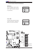
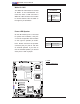
Universal Serial Bus (USB)
There are seven USB 2.0 (Universal
Serial Bus) ports/headers on the
motherboard. Back Panel USB Ports
0 and 1 are located at JUSB1. The
other fi ve are Front Panel Accessible
USB headers. USB Headers 2 and
3, USB Header 4 and 5, and USB6,
located next to the fl oppy drive, pro-
vide front panel USB access. See the
tables on the right for pin defi nitions.
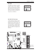
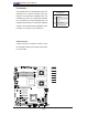
Chassis Intrusion
A Chassis Intrusion header is located
at JL1 on the motherboard. Attach an
appropriate cable from the chassis to
inform you of a chassis intrusion when
the chassis is opened.
Chassis Intrusion
Pin Defi nitions (JL1)
Pin# Defi nition
1 Intrusion Input
2 Ground
A
B
C
A. Backpanel USB 0/1
B. Front Panel USB 2/3
C. Front Panel USB 4/5
D. Front Panel USB 6
E. Chassis Intrusion
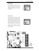
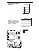
Back Panel USB
(USB0/1)
Pin# Defi nitions
1 +5V
2 PO-
3PO+
4 Ground
5N/A
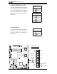
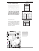
Front Panel USB
Pin Defi nitions (USB 2/3/4)
USB2/4
Pin # Defi nition
USB3
Pin # Defi nition
1 +5V 1 +5V
2 PO- 2 PO-
3PO+ 3 PO+
4 Ground 4 Ground
5 Key 5 No connection
D
E