
User's Manual
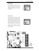

2-16
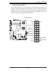
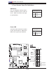
X7DWE User's Manual
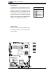
JBT
JWOL1
JPL1
JWD
JPG1
JI2C2
JI2C4
JI2C1
JI2C3
J8
JPT1
SPKR
JD1
J18
JP2
JOH1
JL1
JP1
J7
FAN6
FAN5
FAN1
FAN2
FAN3
FAN4
LED5
LED6
LE1
USB6
T-SGPIO2
USB4/5
USB2/3
COM2
LAN2
LAN1
PWR
BANK1
COM1
VGA
USB0/1
BANK2
KB/MS
DIMM1A
DIMM1B
DIMM2A
DIMM2B
CPU2
CPU1
Slot5 PCI-E x8
Slot6 PCI-E x8
Slot7 SIMLP
Slot4 PCI-E x8
Slot1 PCI-X 133MHz
Slot 2 PCI-E x4
Slot 0 PCI-U
I-SATA5
I-SATA4
FLOPPY
I-SATA0
I-SATA2
I-SATA1
I-SATA3
X7DWE
IDE#1
SMB
FP CTRL
JPL2
Super I/O
LAN
CTRL
Intel 5400
North Bridge
Slot3 PCI-E x8
Intel ESB2
South Bridge
BIOS
T-SGPIO1
VGA
CTRL
24-Pin ATX PWR
8-Pin PWR
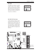
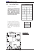
Fan Headers
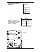
The X7DWE has six chassis/system/CPU fan
headers (Fan1 to Fan6). All these 4-pin fans
headers are backward compatible with the
traditional 3-pin fans. The onboard fan speeds
are controlled by Thermal Management via
Hardware Monitoring in the Advanced Setting
in BIOS. (The Default setting is Disabled.) See
the table on the right for pin defi nitions.
Fan Header
Pin Defi nitions
Pin# Defi nition
1 Ground
2 +12V
3 Tachometer
4 PWR Modulation
B
C
G
F
E
D
A
A. Fan 1
B. Fan 2
C. Fan 3
D. Fan 4
E. Fan 5
F. Fa n 6
G. VGA
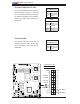
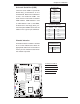
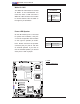
VGA Connector
A VGA connector is located at JVGA1 on the
I/O backplane. Refer to the board layout below
for the location.