
User's Manual

2-18
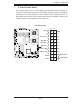
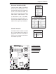
X7DWE User's Manual
JBT
JWOL1
JPL1
JWD
JPG1
JI2C2
JI2C4
JI2C1
JI2C3
J8
JPT1
SPKR
JD1
J18
JP2
JOH1
JL1
JP1
J7
FAN6
FAN5
FAN1
FAN2
FAN3
FAN4
LED5
LED6
LE1
USB6
T-SGPIO2
USB4/5
USB2/3
COM2
LAN2
LAN1
PWR
BANK1
COM1
VGA
USB0/1
BANK2
KB/MS
DIMM1A
DIMM1B
DIMM2A
DIMM2B
CPU2
CPU1
Slot5 PCI-E x8
Slot6 PCI-E x8
Slot7 SIMLP
Slot4 PCI-E x8
Slot1 PCI-X 133MHz
Slot 2 PCI-E x4
Slot 0 PCI-U
I-SATA5
I-SATA4
FLOPPY
I-SATA0
I-SATA2
I-SATA1
I-SATA3
X7DWE
IDE#1
SMB
FP CTRL
JPL2
Super I/O
LAN
CTRL
Intel 5400
North Bridge
Slot3 PCI-E x8
Intel ESB2
South Bridge
BIOS
T-SGPIO1
VGA
CTRL
24-Pin ATX PWR
8-Pin PWR
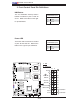
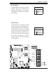
Wake-On-LAN
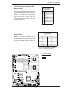
The Wake-On-LAN header is located
at JWOL1 on the motherboard. You
must also have a LAN card with a
Wake-On-LAN connector and a cable
to use this feature. See the table on
the right for pin defi nitions.
Wake-On-LAN
Pin Defi nitions
Pin# Defi nition
1 +5V Standby
2 Ground
3 Wake-up
A
B
A. WOR
B. PWR LED/Speaker
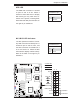
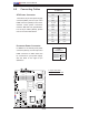
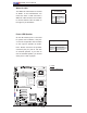
Power LED/Speaker
On the JD1 header, pins 1-3 are used
for power LED indication, and pins
4-7 are for the speaker. See the table
on the right for speaker pin defi ni-
tions. Please note that the speaker
connector pins (4-7) are for use with
an external speaker. If you wish to
use the onboard speaker, you should
close pins 6-7 with a jumper.
Speaker Connector
Pin Setting Defi nition
Pins 6-7 Internal Speaker
Pins 4-7 External Speaker