
User's Manual

Chapter 2: Installation
2-21
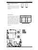
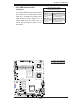
JBT
JWOL1
JPL1
JWD
JPG1
JI2C2
JI2C4
JI2C1
JI2C3
J8
JPT1
SPKR
JD1
J18
JP2
JOH1
JL1
JP1
J7
FAN6
FAN5
FAN1
FAN2
FAN3
FAN4
LED5
LED6
LE1
USB6
T-SGPIO2
USB4/5
USB2/3
COM2
LAN2
LAN1
PWR
BANK1
COM1
VGA
USB0/1
BANK2
KB/MS
DIMM1A
DIMM1B
DIMM2A
DIMM2B
CPU2
CPU1
Slot5 PCI-E x8
Slot6 PCI-E x8
Slot7 SIMLP
Slot4 PCI-E x8
Slot1 PCI-X 133MHz
Slot 2 PCI-E x4
Slot 0 PCI-U
I-SATA5
I-SATA4
FLOPPY
I-SATA0
I-SATA2
I-SATA1
I-SATA3
X7DWE
IDE#1
SMB
FP CTRL
JPL2
Super I/O
LAN
CTRL
Intel 5400
North Bridge
Slot3 PCI-E x8
Intel ESB2
South Bridge
BIOS
T-SGPIO1
VGA
CTRL
24-Pin ATX PWR
8-Pin PWR
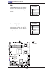
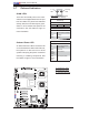
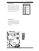
2-6 Jumper Settings
Explanation of
Jumpers
To modify the operation of the mother-
board, jumpers can be used to choose
between optional settings. Jumpers cre-
ate shorts between two pins to change
the function of the connector. Pin 1
is identifi ed with a square solder pad
on the printed circuit board. See the
motherboard layout pages for jumper
locations.
Note: On two pin jumpers,
"Closed" means the jumper
is on and "Open" means the
jumper is off the pins.
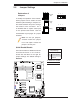
Connector
Pins
Jumper
Cap
Setting
Pin 1-2 short
3 2 1
3 2 1
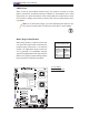
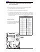
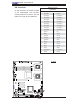
GLAN Enable/Disable
JPL1/JPL2 enable or disable the GLAN
Port1/GLAN Port2 on the mother-
board. See the table on the right for
jumper settings. The default setting is
Enabled.
GLAN Enable
Jumper Settings
Pin# Defi nition
1-2 Enabled (default)
2-3 Disabled
A
A. GLAN Port 1 Enable
B. GLAN Port 2 Enable
B