SUPER SUPER i2DMR-8G2 SUPER i2DMR-iG2 USER’S MANUAL Revision 1.
The information in this User’s Manual has been carefully reviewed and is believed to be accurate. The vendor assumes no responsibility for any inaccuracies that may be contained in this document, makes no commitment to update or to keep current the information in this manual, or to notify any person or organization of the updates. Please Note: For the most up-to-date version of this manual, please see our web site at www.supermicro.com.
Preface Preface About This Manual This manual is written for system integrators, PC technicians and knowledgeable PC users. It provides information for the installation and use of the SUPER i2DMR-8G2/i2DMR-iG2 motherboard. The SUPER i2DMR-8G2/ i2DMR-iG2 supports single or dual Intel Itanium ® 2 processors at a 400 MHz front side bus.
SUPER i2DMR-8G2/i2DMR-iG2 User's Manual Table of Contents Preface About This Manual ...................................................................................................... iii Manual Organization ................................................................................................... iii Chapter 1: Introduction 1-1 Overview ......................................................................................................... 1-1 Checklist .....................................
Table of Contents Overheat LED ......................................................................................... 2-14 Reset Button ........................................................................................... 2-15 Power Button ......................................................................................... 2-15 Universal Serial Bus (USB0/1, USB2/3) ............................................ 2-15 Front Panel Universal Serial Bus Headers (USB4/5) ......................
SUPER i2DMR-8G2/i2DMR-iG2 User's Manual 3-2 Technical Support Procedures .................................................................... 3-2 3-3 Frequently Asked Questions ........................................................................ 3-3 3-4 Returning Merchandise for Service ............................................................ 3-4 Chapter 4: BIOS 4-1 Introduction .......................................................................................................
Chapter 1: Introduction 1-1 Introduction Chapter 1 Introduction Overview Checklist Congratulations on purchasing your computer motherboard from an acknowledged leader in the industry. Supermicro boards are designed with the utmost attention to detail to provide you with the highest standards in quality and performance. Check that the following items have all been included with your motherboard. If anything listed here is damaged or missing, contact your retailer.
SUPER i2DMR-8G2/i2DMR-iG2 User's Manual Contacting Supermicro Introduction Headquarters Address: Tel: Fax: Email: Web Site: SuperMicro Computer, Inc. 980 Rock Ave. San Jose, CA 95131 U.S.A. +1 (408) 503-8000 +1 (408) 503-8008 marketing@supermicro.com (General Information) support@supermicro.com (Technical Support) www.supermicro.com Europe Address: Tel: Fax: Email: SuperMicro Computer B.V.
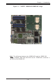
Chapter 1: Introduction Introduction Figure 1-1. SUPER i2DMR-8G2/i2DMR-iG2 Image Note: The difference between the i2DMR-8G2 and the i2DMR-iG2: There is Adaptec 7902 Ultra 320 SCSI on the i2DMR-8G2, and there is no SCSI on the i2DMR-iG2.
SUPER i2DMR-8G2/i2DMR-iG2 User's Manual Figure 1-2. SUPER i2DMR-8G2/i2DMR-iG2 Motherboard Layout (not drawn to scale) 1 J16 5 DIMM5 J15 DIMM2 J13 DIMM6 J14 MRH-D J6 J1 J5 J27 SMB PW PWR Pod (VRM) J30 3 7 J12 PW Pod (VRM)(top) 4 DIMM4 J9 ATI-RAGE _XL(bottom) DIMM8 J10 WD Reset VGA Enabled JV1 PCI-X (256 Pin) J19 SNC (North Bridge) Battery SCSI J A 1 Enable 7902 SCSI Controller J3 SCSI Ch.
Chapter 1: Introduction Quick Reference (i2DMR-8G2/i2DMR-iG2) Jumper Description CN1, CN3 SCSI Cha.A(CN3)/Cha.
SUPER i2DMR-8G2/i2DMR-iG2 User's Manual Motherboard Features CPU Introduction • Two Intel Itanium 2 Processor sockets and power pod sites support: Single or dual Intel ® Itanium 2TM processors at a 400 MHz front side bus (system) speed up to 1.5 GHz, 6MB L3 Cache. (*Notes: Please refer to the support section of our web site for a complete listing of supported processors (http:// www.supermicro.com/TECHSUPPORT/TechSupport.
Chapter 1: Introduction BIOS • 6-MB AMI ® Flash BIOS (total of 6 BIOS chips) • PCI 2.2, BIOS chips, Plug and Play (PnP), SMBIOS 2.
SUPER i2DMR-8G2/i2DMR-iG2 User's Manual • Up to 6 USB 2.
Processor 1 Introduction Chapter 1: Introduction Processor 2 16GB Max. DDR200 MRH_D MRH_D LPC Bus IDE1 USB # 0,1,2, 3,4,5 UDMA100 UDMA100 VGA SNC IDE2 MRH_D 3x1MB FWH PCI32bit USB 2.0 MRH_D Hublink0 ICH4 SIOH Hublink1 P64H2 82546 PCIX-133 2GLAN Ports PCIX-100 Hublink2 LPC Bus DIMM1 DIMM5 DIMM2 DIMM6 DIMM3 DIMM7 DIMM4 DIMM8 VXB Slot LPC 3x1MB Super FWH I/O IPMI SCSI 7902 P64H2 COM1 Figure 1-9.
SUPER i2DMR-8G2/i2DMR-iG2 User's Manual 1-2 Chipset Overview Introduction Built upon the functionality and the capability of the Intel E8870 (870) chipset, the i2DMR-8G2/i2DMR-iG2 motherboard provides the performance and feature set required for high-end server platforms with configuration options optimized for communications, presentation, storage, computation or database applications.
Chapter 1: Introduction Complementary Components include: The ICH4 is the fourth-generation I/O Controller Hub subsystem that integrates many of the input/output functions of the chipset, including a twochannel ATA100 Bus Master IDE controller. The ICH4 also interfaces with PCI and various communications ports. Nearly all communications between the GMCH and the ICH4 takes place over the hub Interface, which is a 66 MHz/266 MB/s bus.
SUPER i2DMR-8G2/i2DMR-iG2 User's Manual CPU Overheat LED and Control Introduction This feature is available when the user enables the CPU overheat warning function in the BIOS. This allows the user to define an overheat temperature. When this temperature is exceeded, fans will speed up, and the warning LED is triggered. Auto-Switching Voltage Regulator for the CPU Core The auto-switching voltage regulator for the CPU core can support up to 20A current and auto-sense voltage IDs ranging from 1.1V to 1.
Chapter 1: Introduction mended that you also install a power surge protector to help avoid problems 1-7 Super I/O The disk drive adapter functions of the Super I/O provides two high-speed, 16550 compatible serial communication ports (UARTs). Each UART includes a 16-byte send/receive FIFO, a programmable baud rate generator, complete modem control capability and a processor interrupt system. Both UARTs provide legacy speed with baud rate of up to 115.
SUPER i2DMR-8G2/i2DMR-iG2 User's Manual Notes Introduction 1-14
Chapter 2: Installation Chapter 2 Installation 2-1 Static-Sensitive Devices Electric-Static-Discharge (ESD) can damage electronic components. To prevent damage to your system board, it is important to handle it very carefully. The following measures are generally sufficient to protect your equipment from ESD. Precautions • Use a grounded wrist strap designed to prevent static discharge. • Touch a grounded metal object before removing the board from the antistatic bag.
SUPER i2DMR-8G2/i2DMR-iG2 User's Manual 2-2 Itanium2 Processor and Heatsink Installation ! When handling the processor package, avoid placing direct pressure on the label area of the fan. Also, do not place the motherboard on a conductive surface, which can damage the BIOS battery and prevent the system from booting up. IMPORTANT: Always connect the power cord last and always remove it before adding, removing or changing any hardware components.
Chapter 2: Installation B. Installing the Heatsink Retention Mechanism on the Motherboard 1. Place the retention mechanism (P/N SKT-0147-RM-IT2) on the motherboard as shown in the picture below: 2. Secure the retention mechanism onto the motherboard by screwing three (3) 6-32 4.5MM screws into the mounting holes on the back of the motherboard. 1.) Place the retention mechanism on the motherboard 2.) Screw in three 6-32 4.
SUPER i2DMR-8G2/i2DMR-iG2 User's Manual C. Installing Motherboard into chassis *Note: To optimize the functionality and the capability of the i2DMR-8G2/ i2DMR-iG2, we strongly recommend that the i2DMR-8G2/i2DMR-iG2 be installed in Supermicro's proprietary chassis only-the SC813HS-500W (*for 1 U), SC823HS-500W (*for 2U). 1. Locate six(6) 6-32 8mm screws in the retention mechanism shipping package. 2.
Chapter 2: Installation D. Installing and securing the Itanium 2 CPU onto the motherboard 1. Insert the Itanium 2 CPU into the CPU1 Socket. Make sure that CPU Pin 1 is aligned with the cut angle of the CPU socket. (*See Note) as shown in the picture below: CPU1 Socket Itanium 2 CPU 2. Use an M2.5 Hex Key to secure the Itanium 2 CPU as shown in the picture below: Use an M 2.5 Hex Key to secure the CPU. 3. Repeat Step 1 and Step 2 to install the second Itanium2 CPU as needed.
SUPER i2DMR-8G2/i2DMR-iG2 User's Manual E. Installing and securing the Power Pod onto the Itanium 2 CPU (*Notes: 1.The CPU Power Pod is a VRM mechanism specially designed for the Itanium 2 processors.) 1. Locate the opening slot on the CPU Power Pod, and align the opening slot with the Itanium2 CPU installed on the motherboard. 2. Carefully push the Edge Connector of the Power Pod toward the CPU until the Signal Pins on both edges of the CPU are fully seated in the Edge Connector and you hear a click.
Chapter 2: Installation 3. Locate four(4) M3 screws in the VRM-008 package. Secure the Power Pod onto the motherboard with four(4) M3 screws as shown in the picture below: 3.) Secure the Power Pod onto the motherboard with four(4) M3 screws. 4. Repeat Step 1 and Step 2 to install the second Itanium2 CPU (w/Power Pod) as needed.
SUPER i2DMR-8G2/i2DMR-iG2 User's Manual F. Installing the Heatsink on the CPU(*for CPU w/o Heatsink only) (*Warning: Do not apply any thermal grease to the heatsink-the required amount of thermal grease has already been applied.) (*Note: To maximizing the cooling effect of the i2DMR-8G2/iG2, we strongly recommend that Supermicro's proprietary heatsinks (SNK-046) be used with the Itanium 2 CPUs.) 1.
Chapter 2: Installation 3. Secure the heatsink onto the CPU by tightening all four screws as shown in Figure 3. 4. Repeat the above steps 1-3 to install the second heatsink on the second CPU if needed as shown in the Figure 4. Figure 4 The i2DMR-8G2/iG2 with two heatsinks installed G. Connecting AC Power to the motherboard and the Power Pods 1. Connect the 24-pin power connector from the AC Power Supply to the motherboard. (Refer to Page 1-4 for the locations of power connectors.) 2.
SUPER i2DMR-8G2/i2DMR-iG2 User's Manual 2-3 Installing DIMMs Note: Check the Supermicro web site for recommended memory modules: http://www.supermicro.com/TECHSUPPORT/FAQs/Memory_vendors.htm CAUTION Exercise extreme care when installing or removing DIMM modules to prevent any possible damage. Also note that the memory is interleaved to improve performance (see step 1). DIMM Installation 1.
Chapter 2: Installation To Remove: Use your thumbs to gently push near the edge of both ends of the module. This should release it from the slot. 2-4 I/OPorts/Control Panel Connectors The I/O ports are color coded in conformance with the PC 99 specification. See Figure 2-3 below for the colors and locations of the various I/O ports. Figure 2-3.
SUPER i2DMR-8G2/i2DMR-iG2 User's Manual Front Control Panel (U66) U66 contains header pins for various buttons and indicators that are normally located on a control panel at the front of the chassis. These connectors are designed specifically for use with Supermicro server chassis. See the figure below for the descriptions of the various control panel buttons and LED indicators. Refer to the following section for descriptions and pin definitions.
Chapter 2: Installation 2-5 Connecting Cables EPS 12V Power Connector There are two 24-pin main power supply connector(J20, J36) on the i2DMR-8G2/i2DMR-iG2. These power connectors meet the SSI EPS 12V specification. (*Only one main power supply is needed.) See the table on the right for pin definitions. EPS 12V Power Supply 24-pin Connectors: J20,J36--Pin Definitions Pin Number Definition Pin Number Definition 1 +3.3V 13 +3.3V 2 +3.
SUPER i2DMR-8G2/i2DMR-iG2 User's Manual HDD LED The HDD LED connection is located on pins 13 and 14 of U66. Attach the hard drive LED cable here to display disk activity (for any hard drives on the system, including SCSI, Serial ATA and IDE). See the table on the right for pin definitions. HDD LED Pin Definitions (U66) Pin Number Definition 13 Vcc 14 HD Active NIC1 LED The NIC (Network Interface Controller) LED connection for the GLAN port is located on pins 11 and 12 of U66.
Chapter 2: Installation Reset Button Reset Pin Definitions (U66) The Reset Button connection is located on pins 3 and 4 of U66. Attach it to the hardware reset switch on the computer case. Refer to the table on the right for pin definitions. Pin Number Definition Reset 3 Ground 4 Power Button Power Butto n Connector Pin Definitions (JF2) The Power Button connection is located on pins 1 and 2 of U66. Momentarily contacting both pins will power on/off the system.
SUPER i2DMR-8G2/i2DMR-iG2 User's Manual Front Panel Universal Serial Bus Header Front Panel Universal Serial Bus(J21) Pin Definitions FPUSB4/FPUSB5 Pin Number 1 2 3 4 5 Two extra USB headers (USB4/ USB5) (J21) can be used for front side USB access. You will need a USB cable to use either connection. Refer to the tables on the right for pin definitions.
Chapter 2: Installation Fan Headers The i2DMR-8G2/i2DMR-iG2 has eight fan headers. See the table on the right for pin definitions. Fan H eader Pin Definitions Pin Number 1 2 3 Definition Ground (black) +12V (red) Tachometer Caution: Fan headers are DC power. Speaker Header CN4 The Speaker header is located on CN4. See the table on the right for speaker pin definitions. Note: The speaker connector pins are for use with an external speaker.
SUPER i2DMR-8G2/i2DMR-iG2 User's Manual Power Fault Connect a cable from your power supply to the U62 header to provide warning of power supply failure. This warning signal is passed through the PWR_LED pin on U66 to indicate of a power failure on the chassis. See the table on the right for pin definitions.
Chapter 2: Installation 2-6 Jumper Settings Explanation of Jumpers To modify the operation of the motherboard, jumpers can be used to choose between optional settings. Jumpers create shorts between two pins to change the function of the connector. Pin 1 is identified with a square solder pad on the printed circuit board. See the motherboard layout pages for jumper locations.
SUPER i2DMR-8G2/i2DMR-iG2 User's Manual Watch Dog J31 controls Watch Dog, a system monitor that takes action when a software application freezes the system. Pins 1-2 will have WD reset the system if a program freezes. Pins 2-3 will generate a non-maskable interrupt for the program that has frozen (requires software implementation). Watch Dog must also be enabled in BIOS. VGA Enable/Disable JV1 allows you to enable or disable the VGA port. The default position is on pins 1 and 2 to enable VGA.
Chapter 2: Installation Force-Power-On Enable/ Disable Jumper J23, located next to the 24Pin power connector, allows you to enable or disable the function of Force-Power-On. If enabled, the power will always stay on automatically. If this function disabled, the user needs to press the power button to power on the system.
SUPER i2DMR-8G2/i2DMR-iG2 User's Manual 2-8 COM Port, IDE, IPMI and SCSI Connections Note the following when connecting the hard disk drive cable: • A red mark on a wire typically designates the location of pin 1. COM Port 1 (J5) & COM 2 Header (J38) The COM Port 1 is located on J5, and the COM 2 Header is located on J38. IDE Connectors There are no jumpers to configure the onboard IDE#1 and #2 connectors (at J37 and J35, respectively). See the table on the right for pin definitions.
Chapter 2: Installation IPMI J26 is designated as the IPMI Socket for the i2DMR-8G2/i2DMRiG2 Motherboard. Ultra 320 SCSI Connectors (*i2DMR-8G2 only) Refer to the table below for the pin definitions of the Ultra 320 SCSI connectors: SCSI A (located on J18), and SCSI B (located on J3.
SUPER i2DMR-8G2/i2DMR-iG2 User's Manual Notes 2-24
Chapter 3: Troubleshooting Chapter 3 Troubleshooting 3-1 Troubleshooting Procedures Use the following procedures to troubleshoot your system. If you have followed all of the procedures below and still need assistance, refer to the ‘Technical Support Procedures’ and/or ‘Returning Merchandise for Service’ section(s) in this chapter. Note: Always disconnect the power cord before adding, changing or installing any hardware components.
SUPER i2DMR-8G2/i2DMR-iG2 User's Manual and off to test the system. 5. The battery on your motherboard may be old. Check to verify that it still supplies ~3VDC. If it does not, replace it with a new one. No Video 1. If the power is on but you have no video, remove all the add-on cards and cables. 2. Use the speaker to determine if any beep codes exist. Refer to the Appendix for details on beep codes. 3. Make sure that the CPU is securely locked in the CPU socket. 4.
Chapter 3: Troubleshooting 3-2 Technical Support Procedures Before contacting Technical Support, please take the following steps. Also, note that as a motherboard manufacturer, Super Micro does not sell directly to end-users, so it is best to first check with your distributor or reseller for troubleshooting services. They should know of any possible problem(s) with the specific system configuration that was sold to you. 1.
SUPER i2DMR-8G2/i2DMR-iG2 User's Manual Question: How do I update my BIOS? Answer: It is recommended that you do not upgrade your BIOS if you are experiencing no problems with your system. Updated BIOS files are located on our web site at http://www.supermicro.com. Please check our BIOS warning message and the information on how to update your BIOS on our web site. Also, check the current BIOS revision and make sure it is newer than your BIOS before downloading.
Chapter 4: AMI BIOS Chapter 4 AMIBIOS 4-1 Introduction This chapter describes the AMIBIOS for the i2DRM-8G2/i2DRM-iG2. The AMI ROM BIOS is stored in a Flash EEPROM and can be easily upgraded using a floppy disk-based program. This chapter describes the basic navigation of the AMI BIOS Setup Utility setup screens. Starting BIOS Setup Utility To enter the AMI BIOS Setup Utility screens, hit the key while the system is booting-up.
SUPER i2DMR-8G2/i2DMR-iG2 User’s Manual 4-2 Main Setup When you first enter the BIOS Setup Utility, you will enter the Main setup screen. You can always return to the Main setup screen by selecting the Main tab on the top of the screen. The Main BIOS Setup screen is shown below. When you select the Main Setup, the following items will be automatically displayed: AMI BIOS Version BIOS Biult Date BIOS ID System Memory Language Menu This option allows you to set the default Language used by the BIOS.
Chapter 4: AMI BIOS keyboard. Press the key or the keys to move between fields. The date must be entered in DAY/MM/DD/YY format. The time is entered in HH:MM:SS format. ( *Note: The time is in 24-hour format. For example, 5:30 A.M. appears as 05:30:00, and 5:30P.M. as 17:30:00.) 4-3 Advanced BIOS Setup The Advanced BIOS Setup screen and sub menus are listed below: Setup Warning When you first enter the Advanced Setup screen, the Setup Warning will be displayed.
SUPER i2DMR-8G2/i2DMR-iG2 User’s Manual Serial Port1 Address/Serial Port2 Address This option specifies the base I/O port addresses and Interrupt Request addresses of Serial Port 1 and Serial Port2. Select "Disabled" to prevent the serial ports from accessing any system resources. When this option is set to Disabled, the serial ports physically becomes unavailable . The options are: "Enabled", and "Disabled." The default setting for Serial Port1 is "Enabled".
Chapter 4: AMI BIOS Primary IDE Master/Slave, Secondary IDE Master/Slave Sub Menu From the Advanced Setup screen, press to access this sub menu for the primary and secondary IDE master and slave drives. Use this screen to select options for the Primary and Secondary IDE drives. Use the up and down keys to select an item. Use the and keys to change the value of the selected option. Type Select the type of device connected to the system.
SUPER i2DMR-8G2/i2DMR-iG2 User’s Manual DMA Mode Select Auto to allow the BIOS to auto detect the DMA mode. Use this value if the IDE disk drive support cannot be determined. Select SWDMA0 to allow the BIOS to use Single Word DMA mode 0. It has a data transfer rate of 2.1 MBs. Select SWDMA1 to allow the BIOS to use Single Word DMA mode 1. It has a data transfer rate of 4.2 MBs. Select SWDMA2 to allow the BIOS to use Single Word DMA mode 2. It has a data transfer rate of 8.3 MBs.
Chapter 4: AMI BIOS ATA(PI) Detect Time Out The feature allows AMI BIOS to set the time out value for detecting ATA(PI) devices . The options are:"0", "5", "10", "15", "20", "25" and "30." ATA(PI) 80Pin Cable Detection This feature allows the BIOS to auto-detect 80Pin ATA(PI) Cable. The options are:"Host & Device", "Host" and "Device." ! BIOS Settings Configuration This item allows the user to configure the system's boot settings.
SUPER i2DMR-8G2/i2DMR-iG2 User’s Manual !System Health Monitor This feature allows the BIOS to automatically display the status of the following items: Advanced System Health CPU Overheat CPUI Temperature/CPU2 Temperature (*for 2U systems) Voltage Status Fan Speeds 4-8
Chapter 4: AMI BIOS !Peripheral Device Configuration This feature allows the user to configure Peripheral Device settings Power Loss Control This setting allows you to choose how the system will react when power returns after an unexpected loss of power. Options are "Stay Off", "Power On" and "Last State." Watch Dog Timer This setting is used to enable or disabled the Watch Dog Timer function. It must be used in conjunction with the J31 jumper (see Chapter 2 for details).
SUPER i2DMR-8G2/i2DMR-iG2 User’s Manual !UBS Configuration This feature allows the user to configure USB settings USB Function Select "Enabled" to enable the USB Host Controller. The options are "Disabled", and "Enabled." Legacy USB Support Select "Enabled" to enable the support for USB Legacy. The options are "Disabled", and "Enabled.
Chapter 4: AMI BIOS 4-4 PCI/PnP Configuration This feature allows the user to set PCI/PnP configurations: PCI Latency Timer This option sets the latency of all PCI devices on the PCI bus. The default setting is "64." Select "32" to set the PCI latency to 32 PCI clock cycles. Select "64" to set the PCI latency to 64 PCI clock cycles. Select "96" to set the PCI latency to 96 PCI clock cycles. Select "128" to set the PCI latency to 128 PCI clock cycles.
SUPER i2DMR-8G2/i2DMR-iG2 User’s Manual !Hardware Health Monitoring H/W Health Function Select "Enabled" to enable the function of Hardware Health Monitoring Device. The Options are "Enabled" and "Disabled". Overheat Temperature Trips The feature allows the user to set the CPU temperature threshold. The options range from "65 oC" to "90 oC. The default setting is "78 o C". 4-5 Security Settings AMI BIOS provides a Supervisor and a User password.
Chapter 4: AMI BIOS 4-6 Exit Options Select the Exit tab from the BIOS Setup Utility screen to enter the Exit BIOS Setup screen. Exit Saving Changes When you have completed the system configuration changes, select this option to leave BIOS Setup and reboot the computer, so the new system configuration parameters can take effect. Select Save Changes and Exit from the Exit menu and press .
SUPER i2DMR-8G2/i2DMR-iG2 User’s Manual Discarding Changes Select this option and press to discard all the changes and return to the BIOS Utility Program.
Chapter 5: Software Installation Chapter 5 Software Drivers and the Operating System Installation After all the hardware has been installed, you need to install the operating system, and other software drivers. The necessary drivers are all included on the Supermicro CDs that came packaged with your motherboard.
SUPER i2DMR-8G2/i2DMR-iG2 User's Manual 5-2 Flash AMI BIOS: 1. Obtain a USB Pen, or a USB storage device (2.0 recommended). 2. From our web site, download the following two files into the USB pen or device: [amiflash.efi], and [bios.rom] (*The link to the files is: www.supermicro.com) 3. Connect the USB device to one of the USB ports (*See Page 1-4 for USB port locations.) 4. Bootup the system with the USB pen connected to a USB port. The system will boot to the “EFI Boot Manager”.
Chapter 5: Software Installation The location of the USB device (Example) Locate the USB device (Example) 6. At the Shell command prompt, type: Shell> fsX: (*X: is the number of sector which your USB pen is located at.) (*This command will change the directory from [Shell] to [fsX]) 7. Now, you can start flashing BIOS by typing: fsX:\> amiflash bios.rom (*X: is the sector number that your USB pen is located at.) 8.
SUPER i2DMR-8G2/i2DMR-iG2 User's Manual 9. When the fsx directory appears, type in the file name at the prompt. fsx:\ amiflash ami64.rom (eg: for the example shown above, at the prompt, type ami64.rom and press as shown below: Then, the system will start loading the BIOS Image file.
Chapter 5: Software Installation After the BIOS Image file is loaded, the following screen will appear: 10. When asked "Reset NVRAM to default value? (y/n), type "y" at the prompt, if you want to reset all default values after flashing the BIOS.(*y: This will reset your NVRAM which typically resets your boot options in EFI to manufacturer defaults. If you previously added options to boot from CDROM or Windows, these will disappear after NVRAM is reset, and in this case you will have to re-add the options.
SUPER i2DMR-8G2/i2DMR-iG2 User's Manual Brief instruction for adding the "CDROM" boot option in EFI: 1. Power on the system and go into the “EFI Boot Manager” 2. Select “Boot Option Maintenance Menu." 3. Select “Add a Boot Option.” 4. Select “Removable Media Boot [Acpi(PNP0A03,0)/ Pci(1F|1)/ATA(Secondary,Master)]” (* Please note: if your CDROM drive is connected to the primary IDE connector, you must choose it accordingly.) 5. Enter a new description such as “CDROM.” 6.
Chapter 5: Software Installation Brief instruction for IA64 OS (include Windows XP 64bit, Windows 2003 Enterprise 64bit, Red Hat Linux 64 bit and SUSE Linux 64bit for Itanium) Installation on IDE hard drive: (*Note: The Itanium2 board does not have a floppy connector, so the user cannot install Windows driver through a floppy device. This procedure uses ramdisk to add the boot device driver in EFI so that Windows OS will automatically pick up driver from there.) 1.
SUPER i2DMR-8G2/i2DMR-iG2 User's Manual 11. At the Shell command prompt, type: Shell> exit (*This command will exit EFI Shell and go back to “EFI Boot Manager.”) 12. Select “CDROM” boot option to boot from Windows OS installation CD after you have already added CDROM boot option under EFI Boot Manager. 13. Follow OS instruction to setup OS.
Appendix A: BIOS POST Checkpoint Codes Appendix A BIOS POST Checkpoint Codes When AMIBIOS performs the Power On Self Test, it writes checkpoint codes to I/O port 0080h. If the computer cannot complete the boot process, diagnostic equipment can be attached to the computer to read I/O port 0080h. A-1 IA-32 Post Codes The IA-32 Post Codes are listed in order of execution: Checkpoint Code Description D0h The NMI is disabled. Power on delay is starting.
SUPER i2DMR-8G2/i2DMR-iG2 User’s Manual Checkpoint Code Description 03h The NMI is disabled. Next, checking for a soft reset or a power on condition. The BIOS stack has been built. Next, disabling cache memory. Uncompressing the POST code next. Next, initializing the CPU and the CPU data area. The CMOS checksum calculation is done next. The CMOS checksum calculation is done. Initializing the CMOS status register for date and time next. The CMOS status register is initialized.
Appendix A: BIOS POST Checkpoint Codes Checkpoint Code Description 24h The configuration required before interrupt vector initialization has completed. Interrupt vector initialization is about to begin. Interrupt vector initialization is done. Clearing the password if the POST DIAG switch is on. Any initialization before setting video mode will be done next. Initialization before setting the video mode is complete. Configuring the monochrome mode and color mode settings next.
SUPER i2DMR-8G2/i2DMR-iG2 User’s Manual Checkpoint Code Description 47h 48h 49h 4Bh 4Ch 4Dh 4Eh 4Fh 50h 51h 52h 53h 54h 57h 58h 59h The memory pattern has been written to extended memory. Writing patterns to the base 640 KB memory next. Patterns written in base memory. Determining the amount of memory below 1 MB next. The amount of memory below 1 MB has been found and verified. Determining the amount of memory above 1 MB memory next. The amount of memory above 1 MB has been found and verified.
Appendix A: BIOS POST Checkpoint Codes Checkpoint Code Description 60h The DMA page register test passed. Performing the DMA Controller 1 base register test next. The DMA controller 1 base register test passed. Performing the DMA controller 2 base register test next. The DMA controller 2 base register test passed. Programming DMA controllers 1 and 2 next. Completed programming DMA controllers 1 and 2. Initializing the 8259 interrupt controller next. Completed 8259 interrupt controller initialization.
SUPER i2DMR-8G2/i2DMR-iG2 User’s Manual Checkpoint Code Description 95h Initializing the bus option ROMs from C800 next. See the last page of this chapter for additional information. Initializing before passing control to the adaptor ROM at C800. Initialization before the C800 adaptor ROM gains control has completed. The adaptor ROM check is next. The adaptor ROM had control and has now returned control to BIOS POST. Performing any required processing after the option ROM returned control.
Appendix A: BIOS POST Checkpoint Codes A-2 Common Debug Codes Common Debug Codes for the motherboard are listed below: Checkpoints DS4 On On Off Off Code Description DS3 On: Off: On: Off: SNC found and start memory sizing Initial system memory and SIOH Valid memory and SIOH found ICH4 found A-7
SUPER i2DMR-8G2/i2DMR-iG2 User’s Manual Notes A-8