
Owner's manual

2-12
SUPER i2DMR-8G2/i2DMR-iG2 User's Manual
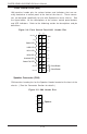
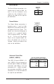
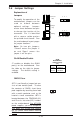
Front Control Panel (U66)
U66 contains header pins for various buttons and indicators that are nor-
mally located on a control panel at the front of the chassis. These connec-
tors are designed specifically for use with Supermicro server chassis. See
the figure below for the descriptions of the various control panel buttons
and LED indicators. Refer to the following section for descriptions and pin
definitions.
Figure 2-4: Front Control Panel-U66 Header Pins
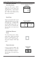
Power Button
Overheat LED
1
NIC1 LED
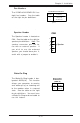
Reset Button
2
Power Fail LED
HDD LED
Power LED
Reset
Pwr
Vcc
Vcc
Vcc
Vcc
Ground
Ground
1920
Vcc
X
Ground
NMI
X
X
NIC2 LED
Speaker
1
2
3
4
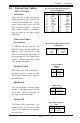
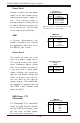
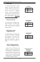
Speaker Connector (CN4)
CN4 contains header pins for the Speaker Header located at the front of the
chassis. (*See the Connector Section for details.)
Figure 2-5: CN4 Header Pins