SUPER X7DB8 X7DBE USER’S MANUAL Revision 1.
The information in this User’s Manual has been carefully reviewed and is believed to be accurate. The vendor assumes no responsibility for any inaccuracies that may be contained in this document, makes no commitment to update or to keep current the information in this manual, or to notify any person or organization of the updates. Please Note: For the most up-to-date version of this manual, please see our web site at www.supermicro.com. Super Micro Computer, Inc.
Preface Preface About This Manual This manual is written for system integrators, PC technicians and knowledgeable PC users. It provides information for the installation and use of X7DB8/X7DBE motherboard. The X7DB8/X7DBE supports the dual Intel Xeon 64-bit quad-core/dual-core processors at a front side bus speed of 1333/1066/667 MHz.
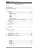
X7DB8/X7DBE User's Manual Table of Contents Preface About This Manual ...................................................................................................... iii Manual Organization ................................................................................................... iii Conventions Used in the Manual .................................................................................. iii Chapter 1: Introduction 1-1 Overview .....................................................
Table of Contents Reset Button ......................................................................................... 2-13 Power Button .......................................................................................... 2-13 2-5 Connecting Cables ......................................................................................... 2-14 ATX Power Connector .......................................................................... 2-14 Processor Power Connector ..................................
X7DB8/X7DBE User's Manual 2-8 Parallel Port, Floppy, SIMLP IPMI, Hard Disk Drive and SCSI Connections .. 2-31 Parallel Port Connector ........................................................................... 2-31 Floppy Connector .................................................................................... 2-32 SIMLP IPMI Slot ...................................................................................... 2-32 IDE Connectors ...................................................................
Chapter 1: Introduction Chapter 1 Introduction 1-1 Overview Checklist Congratulations on purchasing your computer motherboard from an acknowledged leader in the industry. Supermicro boards are designed with the utmost attention to detail to provide you with the highest standards in quality and performance. Check that the following items have all been included with your motherboard. If anything listed here is damaged or missing, contact your retailer.
X7DB8/X7DBE User's Manual Contacting Supermicro Headquarters Address: Super Micro Computer, Inc. 980 Rock Ave. Tel: San Jose, CA 95131 U.S.A. +1 (408) 503-8000 Fax: +1 (408) 503-8008 Email: marketing@supermicro.com (General Information) support@supermicro.com (Technical Support) Web Site: www.supermicro.com Europe Address: Tel: Fax: Email: Super Micro Computer B.V. Het Sterrenbeeld 28, 5215 ML 's-Hertogenbosch, The Netherlands +31 (0) 73-6400390 +31 (0) 73-6416525 sales@supermicro.
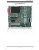
Chapter 1: Introduction X7DB8/X7DBE Image (Note: The drawings and pictures shown in this manual were based on the latest PCB Revision available at the time of publishing of the manual. The motherboard you’ve received may or may not look exactly the same as the graphics shown in the manual.
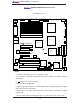
X7DB8/X7DBE User's Manual X7DB8/X7DBE Motherboard Layout (not drawn to scale) VGA J 15 (B a nk 4) DIMM 4A (B a nk 4) J 8B 3 DIMM 3B (B a nk 3) J 8B 2 DIMM 3A (B a nk 3) J 8B 1 DIMM 2B (B a nk 2) J 7B 3 DIMM 2A (B a nk 2) J 7B 2 DIMM 1B (B a nk 1) J 7B 1 DIMM 1A (B a nk J F1 F P C trl Fan1 DIMM 4B J 9B 1 C P U1 PW LED SPK Fan2 J P1 J D1 J 21 P arrallel J PL ort A N1 J US B 1 C O M1 JCOM1 J 9B 2 8-pin P W R J PW3 F a n7 S MBJ PS 17 PSF J 3P J AR 1) LE1 GLAN1 J LAN1 C
Chapter 1: Introduction Quick Reference ( X7DB8/X7DBE) Jumper J27, J28 J3P Description 2 I C Bus to PCI-X/PCI-E Slots 3rd PWR Failure Detect Off (Disabled) JBT1 CMOS Clear See Chapter 2 JCF1 Compact Card Master/Slave Select JPA1 (*X7DB8) SCSI Controller Enable Default Setting Open (Disabled) On (Master) Pins 1-2 (Enabled) JPA2, JPA3 SCSI CHA(JPA2),CHB(JPA3)Term.
X7DB8/X7DBE User's Manual Motherboard Features CPU • Dual Intel® 64-bit Xeon LGA 771 quad-core/dual-core processors at a front side bus speed of 1.333 GHz/1.066 GHz/667 MHz with a system clock speed of 333/267 MHz Memory • Eight 240-pin DIMM sockets with support up to 16 (32) GB DDR2 Fully Buffered (FBD) ECC 667/533 Memory (*See Section 2-3 in Chapter 2 for DIMM Slot Population.
Chapter 1: Introduction ACPI Features • Slow blinking LED for suspend state indicator • Main switch override mechanism • ACPI/ACPM Power Management • Keyboard Wakeup from Soft-off Onboard I/O • Adaptec 7902 dual channel Ultra 320 SCSI with ZCR option (X7DB8 only) • Six SATA2 ports (supporting RAID0, RAID1,10 and 5) • One SIMLP IPMI socket • Intel 82563 Gigabit Ethernet controller supporting two Giga-bit LAN ports • Two EIDE Ultra DMA/100 bus master interfaces supporting one IDE (the blue s
X7DB8/X7DBE User's Manual 667/1067/1333 #0 -#5 3.0 Gb/ S VGA CONN Controller IDE CONN PCI -E XPx8 PCI -X 133 MHz VGA F BD DIMM # 4 A - 4 B PCI E x4 F BD CHNL3 F BD DIMM # 3 A - 3 B F BD CHNL2 AT A 100 PXH #3 E S B2 PC I 32/ 33 MHz US B 2.
Chapter 1: Introduction 1-2 Chipset Overview Built upon the functionality and the capability of the 5000P (Blackford) chipset, the X7DB8/X7DBE motherboard provides the performance and feature set required for dual processor-based servers with configuration options optimized for communications, presentation, storage, computation or database applications. The 5000P (Blackford) chipset supports single or dual Xeon 64-bit quad-core/dual-core processor(s) with front side bus speeds of up to 1.333 GHz.
X7DB8/X7DBE User's Manual 1-3 Special Features Recovery from AC Power Loss BIOS provides a setting for you to determine how the system will respond when AC power is lost and then restored to the system. You can choose for the system to remain powered off (in which case you must hit the power switch to turn it back on) or for it to automatically return to a power- on state. See the Power Lost Control setting in the Advanced BIOS Setup section to change this setting.
Chapter 1: Introduction CPU Fan Auto-Off in Sleep Mode The CPU fan activates when the power is turned on. It continues to operate when the system enters Standby mode. When in sleep mode, the CPU will not run at full power, thereby generating less heat. CPU Overheat LED and Control This feature is available when the user enables the CPU overheat warning function in the BIOS. This allows the user to define an overheat temperature.
X7DB8/X7DBE User's Manual Main Switch Override Mechanism When an ATX power supply is used, the power button can function as a system suspend button to make the system enter a SoftOff state. The monitor will be suspended and the hard drive will spin down. Pressing the power button again will cause the whole system to wake-up. During the SoftOff state, the ATX power supply provides power to keep the required circuitry in the system alive.
Chapter 1: Introduction Note: The + 12V 8-pin Aux. Power Connector is also required to support Intel 64bit CPUs. Failure to provide this extra power will result in CPU PWR Failure. See Section 2-5 for details on connecting the power supply. It is strongly recommended that you use a high quality power supply that meets ATX power supply Specification 2.02 or above. It must also be SSI compliant (info at http://www.ssiforum.org/).
X7DB8/X7DBE User's Manual Notes 1-14
Chapter 2: Installation Chapter 2 Installation 2-1 Static-Sensitive Devices Electro-Static-Discharge (ESD) can damage electronic components. To prevent damage to your system board, it is important to handle it very carefully. The following measures are generally sufficient to protect your equipment from ESD. Precautions • Use a grounded wrist strap designed to prevent static discharge. • Touch a grounded metal object before removing the board from the antistatic bag.
X7DB8/X7DBE User's Manual 2-2 Processor and Heatsink Installation ! When handling the processor package, avoid placing direct pressure on the label area of the fan. (Notes: 1. Always connect the power cord last and always remove it before adding, removing or changing any hardware components. Make sure that you install the processor into the CPU socket before you install the CPU heatsink. 2. Intel's boxed Xeon CPU package contains the CPU fan and heatsink assembly.
Chapter 2: Installation North Center Edge 3. Use your thumb and your index finger to hold the CPU at the North Center Edge and the South Center Edge of the CPU. 4. Align CPU Pin1 (the CPU corner marked with a triangle) against the socket corner that is marked with a South Center Edge gold dot triangle cutout. Socket Key 5. Align the CPU key that is the semicircle cutout below a gold dot against the socket key, the notch on the same side of the triangle cutout on the socket. 6.
X7DB8/X7DBE User's Manual CEK Heatsink Installation Installation of the Heatsink CEK Passive Heatsink 1. Do not apply any thermal grease to the heatsink or the CPU die-the required amount has already been applied. 2. Place the heatsink on top of the CPU so that the four mounting holes are aligned with those on the retention mechanism. Screw#1 Screw#2 3. Screw in two diagonal screws (ie the #1 and the #2 screws) until just snug (-do not fully tighten the screws to avoid possible damage to the CPU.
Chapter 2: Installation 1. Unscrew and remove the heatsink screws from the motherboard in the sequence as show in the picture on the right. 2. Hold the heatsink as shown in the picture on the right and gently wriggle the heatsink to loosen it from the CPU. (Do not use excessive force when wriggling the heatsink!!) 3. Once the CPU is loosened, remove the heatsink from the CPU socket. 4. Clean the surface of the CPU and the heatsink to get rid of the old thermal grease.
X7DB8/X7DBE User's Manual 2-3 Installing DIMMs Note: Check the Supermicro web site for recommended memory modules. CAUTION Exercise extreme care when installing or removing DIMM modules to prevent any possible damage. Also note that the memory is interleaved to improve performance (See step 1). DIMM Installation (See Figure 2-2) 1. Insert the desired number of DIMMs into the memory slots, starting with DIMM #1A.
Chapter 2: Installation Possible System Memory Allocation & Availability System Device Size Physical Memory Remaining (-Available) (4 GB Total System Memory) Firmware Hub flash memory (System BIOS) 1 MB 3.99 Local APIC 4 KB 3.99 Area Reserved for the chipset 2 MB 3.99 I/O APIC (4 Kbytes) 4 KB 3.99 PCI Enumeration Area 1 256 MB 3.76 PCI Express (256 MB) 256 MB 3.51 PCI Enumeration Area 2 (if needed) -Aligned on 256-MB boundary- 512 MB 3.01 VGA Memory 16 MB 2.85 TSEG 1 MB 2.
X7DB8/X7DBE User's Manual 2-4 Control Panel Connectors/IO Ports The I/O ports are color coded in conformance with the PC 99 specification. See Figure 2-3 below for the colors and locations of the various I/O ports. JLAN1 A. Back Panel Connectors/IO Ports SUPER ® 2 4 1 3 7 X7DB8/E 5 6 8 Figure 2-3. Back Panel I/O Port Locations and Definitions Back Panel Connectors 1. Keyboard (Purple) 2. PS/2 Mouse (Green) 3. Back Panel USB Port 0 4. Back Panel USB Port 1 5. COM Port 1 (Turquoise) 6.
Chapter 2: Installation B. Front Control Panel JF1 contains header pins for various buttons and indicators that are normally located on a control panel at the front of the chassis. These connectors are designed specifically for use with Supermicro server chassis. See Figure 2-4 for the descriptions of the various control panel buttons and LED indicators. Refer to the following section for descriptions and pin definitions. Figure 2-4.
X7DB8/X7DBE User's Manual C. Front Control Panel Pin Definitions NMI Button NMI Button Pin Definitions (JF1) The non-maskable interrupt button Pin# Definition header is located on pins 19 and 20 19 Control 20 Ground of JF1. Refer to the table on the right for pin definitions. Power LED Power LED Pin Definitions (JF1) The Power LED connection is located on pins 15 and 16 of JF1. Refer to the table on the right for pin definitions. Pin# Definition 15 +5V 16 Ground A. NMI B.
Chapter 2: Installation HDD LED The HDD LED connection is located HDD LED Pin Definitions (JF1) on pins 13 and 14 of JF1. Attach the hard drive LED cable here to display disk activity (for any hard drives on Pin# Definition 13 +5V the system, including SAS, Serial ATA 14 HD Active and IDE). See the table on the right for pin definitions.
X7DB8/X7DBE User's Manual Overheat/Fan Fail LED (OH) OH/Fan Fail LED Pin Definitions (JF1) Connect an LED to the OH/Fan Fail connection on pins 7 and 8 of JF1 to provide advanced warning of chassis overheating or fan failure. Refer to Pin# Definition 7 Vcc 8 Ground OH/Fan Fail Indicator Status the table on the right for pin definitions.
Chapter 2: Installation Reset Button The Reset Button connection is located on pins 3 and 4 of JF1. Attach it to the Reset Button Pin Definitions (JF1) hardware reset switch on the computer case. Refer to the table on the right for Pin# Definition 3 Reset pin definitions. 4 Ground Power Button The Power Button connection is located on pins 1 and 2 of JF1. Momentarily contacting both pins will power on/off the system.
X7DB8/X7DBE User's Manual 2-5 Connecting Cables ATX Power Connector Pin Definitions Pin# Definition 13 +3.3V 1 +3.3V There are a 24-pin main power sup- 14 -12V 2 +3.3V ply connector(JPW1) and an 8-pin 15 COM 3 COM 16 PS_ON 4 +5V 17 COM 5 COM tors meet the SSI EPS 12V specifica- 18 COM 6 +5V tion. The 4-pin 12V PWR supply is 19 COM 7 COM 20 Res (NC) 8 PWR_OK 21 +5V 9 5VSB 22 +5V 10 +12V 23 +5V 11 +12V 24 COM 12 +3.
Chapter 2: Installation Universal Serial Bus (USB) Back Panel USB (USB#0/1) There are five USB 2.0 (Universal Se- Pin# Definitions rial Bus) ports/headers on the moth- 1 +5V 2 PO- 3 PO+ 4 Ground 5 N/A erboard. Two of them are Back Panel USB ports (USB#0/1:JUSB1), and the other three are Front Panel USB headers (USB#2/3:JUSB2, USB#4: JUSB3). See the tables on the right Front Panel USB Pin Definitions for pin definitions.
X7DB8/X7DBE User's Manual Fan Headers The X7DB8/X7DBE has eight chassis/system fan headers (Fan1 to Fan8) and two CPU Fans Fan Header Pin Definitions (Fans 7/8). (Note: all these fans are 4-pin fans. However, Pins 1-3 of the fan headers are Pin# Definition backward compatible with the traditional 3-pin 1 Ground fans.) See the table on the right for pin defini- 2 +12V tions.
Chapter 2: Installation ATX PS/2 Keyboard and PS/2 Mouse Ports PS/2 Keyboard and Mouse Port Pin Definitions The ATX PS/2 keyboard and the PS/2 Pin# Definition mouse are located at JKM1. See the 1 Data table on the right for pin definitions. (The mouse port is above the key- 2 NC 3 Ground board port. See the table on the right 4 VCC for pin definitions.
X7DB8/X7DBE User's Manual Wake-On-Ring The Wake-On-Ring header is des- Wake-On-Ring Pin Definitions ignated JWOR. This function allows your computer to be "awakened" by an incoming call to the modem when Pin# Definition 1 Ground the system is in the suspend state. 2 Wake-up See the table on the right for pin definitions. You must have a WakeOn-Ring card and cable to use this feature. Wake-On-LAN Wake-On-LAN Pin Definitions (JWOL) The Wake-On-LAN header is located at JWOL on the motherboard.
Chapter 2: Installation GLAN 1/2 (Giga-bit Ethernet Ports) Two G-bit Ethernet ports are desigGLAN1 nated JLAN1 and JLAN2 on the IO GLAN2 backplane. This port accepts RJ45 type cables. Power LED/Speaker On the JD1 header, pins 1-3 are for a power LED and pins 4-7 are for the speaker. See the table on the right for speaker pin definitions. Note: The speaker connector pins are for use with an external speaker. If you wish to use the onboard speaker, you should close pins 6-7 with a jumper.
X7DB8/X7DBE User's Manual Power Fault (PWR Supply Failure) PWR Supply Fail LED Pin Definitions Connect a cable from your power supply to the Power Fail (PSF) header to provide warnings of power supply failure. This warning signal is passed through the PWR_LED pin to indicate of a power failure on the chassis. See the table on the right for pin definitions.
Chapter 2: Installation Overheat LED/Fan Fail (JOH1) Overheat LED Pin Definitions The JOH1 header is used to connect an LED to provide warning of chassis overheating. This LED will blink to indicate a fan failure. Refer to the table Pin# Definition 1 5vDC 2 OH Active OH/Fan Fail LED on right for pin definitions. State Message Solid Overheat Blinking Fan Fail SMB SMB Header Pin Definitions A System Management Bus header is located at J18.
X7DB8/X7DBE User's Manual Power SMB (I2C) Connector PWR SMB Pin Definitions Power SMB (I 2C) Connector (J17) monitors the status of PWR Supply, fan and system temperature status. See the table on the right for pin definitions. Pin# Definition 1 Clock 2 Data 3 PWR Fail 4 Ground 5 +3.3V VGA Connector A VGA connector (JG1) is located next to the COM1 port on the IO backplane. Refer to the board layout below for the location.
Chapter 2: Installation Compact Flash Card PWR Connector A Compact Flash Card PWR Connector Compact Flash Card Power Connector is located at JWF1. For the Jumper Definition Compact Flash Card or the Compact Flash Jumper (JCF1) to work properly, On Compact Flash Power On you will need to connect the Compact Off Compact Flash Power Off Flash Card power cable to JWF1 first. Refer to the board layout below for the location.
X7DB8/X7DBE User's Manual 2-6 Jumper Settings Explanation of Jumpers Connector Pins 3 2 1 3 2 1 To modify the operation of the motherboard, jumpers can be used to choose between optional settings. Jumpers create shorts between two Jumper Cap pins to change the function of the connector. Pin 1 is identified with a Setting square solder pad on the printed circuit Pin 1-2 short board. See the motherboard layout pages for jumper locations.
Chapter 2: Installation CMOS Clear JBT1 is used to clear CMOS. Instead of pins, this "jumper" consists of contact pads to prevent the accidental clearing of CMOS. To clear CMOS, use a metal object such as a small screwdriver to touch both pads at the same time to short the connection. Always remove the AC power cord from the system before clearing CMOS. Note: For an ATX power supply, you must completely shut down the system, remove the AC power cord and then short JBT1 to clear CMOS.
X7DB8/X7DBE User's Manual SCSI Controller Enable/ Disable VGA Enable/Disable Jumper Settings (JPA1) Jumper Setting Jumper JPA1 is used to enable or disable the LSI SCSI controller. The default setting is on pins 1-2 to enable SCSI. See the table on the right for jumper settings. Definition Pins 1-2 Enabled Pins 2-3 Disabled SCSI Termination Enable/ Disable SCSI Term.
Chapter 2: Installation 3rd PWR Supply PWR Fault Detect (J3P) 3rd PWR Supply PWR Fault Jumper Settings Jumper Setting The system can notify you in the event of a power supply failure. This feature available when three power supply units are installed in the chassis with one acting Definition Closed Enabled Open Disabled (*Default) as a backup. If you only have one or two power supply units installed, you should disable this (the default setting) with J3P to prevent false alarms.
X7DB8/X7DBE User's Manual Compact Flash Master/Slave Select Compact Flash Card Master/ Slave Select A Compact Flash Master (Primary)/Slave (Secondary) Select Jumper is located Jumper Definition at JCF1. Close this jumper to enable Compact Flash Card. For the Compact Flash Card or the Compact Flash Jumper Open Slave (Secondary) Closed Master (Primary) (JCF1) to work properly, you will need to connect the Compact Flash Card power cable to JWF1 first. Refer to the board layout below for the location.
Chapter 2: Installation 2-7 Onboard Indicators GLAN LEDs Link Activity LED LED (*Rear View: when viewing it from the rear side of the chassis) There are two GLAN ports on the GLAN Activity Indicator motherboard. Each Gigabit Ethernet LAN port has two LEDs.The yellow LED indicates activity, while Color Status Definition Yellow Flashing Active the link LED may be green, amber or off to indicate the speed of the GLAN Link Indicator connection. See the tables at right for more information.
X7DB8/X7DBE User's Manual Onboard SCSI Activity LED Indicators (*X7DB8 only) There are two Onboard SCSI Activity LED indicators on the X7DB8. DA1 indicates the activity status of SCSI Channel A, and DA2 indicates the activity status of SCSI Channel B. Onboard Power LED There is an Onboard Power LED located on the motherboard. When this LED is lit, the system is on. Be sure to turn off the system and unplug the power cord before removing or installing components. See the layout below for the LED location.
Chapter 2: Installation 2-8 Parallel Port, Floppy Drive, Hard Disk Drive, SIMLP IPMI and SCSI Connections Note the following when connecting the floppy and hard disk drive cables: • The floppy disk drive cable has seven twisted wires. • A red mark on a wire typically designates the location of pin 1. • A single floppy disk drive ribbon cable has 34 wires and two connectors to provide for two floppy disk drives.
X7DB8/X7DBE User's Manual Floppy Connector Floppy Drive Connector Pin Definitions (Floppy) The floppy connector is located next Pin# Definition to the compact flash card slot. See 1 Ground 2 FDHDIN the table below for pin definitions.
Chapter 2: Installation IDE Connectors IDE Drive Connectors Pin Definitions There are two IDE Connectors Pin# Definition (JIDE1: Blue, JIDE2: White) on the 1 Reset IDE 2 Ground 3 Host Data 7 4 Host Data 8 5 Host Data 6 6 Host Data 9 Primary IDE Drive. The white IDE 7 Host Data 5 8 Host Data 10 connector (JIDE2) is designated as 9 Host Data 4 10 Host Data 11 the Secondary IDE Drive, reserved 11 Host Data 3 12 Host Data 12 for Compact Flash Card use only. (See the note below.
X7DB8/X7DBE User's Manual Ultra 320 SCSI Connectors (*X7DB8 only) There are two SCSI connectors on the motherboard. SCSI Channel A is located at JA1, and SCSI Channel B is located at A2. Refer to the table below for the pin definitions of the Ultra 320 SCSI connectors located at JA1 and JA2. A. SCSI Channel A JLAN1 B.
Chapter 3: Troubleshooting Chapter 3 Troubleshooting 3-1 Troubleshooting Procedures Use the following procedures to troubleshoot your system. If you have followed all of the procedures below and still need assistance, refer to the ‘Technical Support Procedures’ and/or ‘Returning Merchandise for Service’ section(s) in this chapter. Note: Always disconnect the power cord before adding, changing or installing any hardware components. Before Power On 1.
X7DB8/X7DBE User's Manual 2. The battery on your motherboard may be old. Check to verify that it still supplies ~3VDC. If it does not, replace it with a new one. 3. If the above steps do not fix the Setup Configuration problem, contact your vendor for repairs. NOTE If you are a system integrator, VAR or OEM, a POST diagnostics card is recommended. For I/O port 80h codes, refer to App. B. Memory Errors 1. Make sure that the DIMM modules are properly and fully installed. 2.
Chapter 3: Troubleshooting • Motherboard model and PCB revision number • BIOS release date/version (this can be seen on the initial display when your system first boots up) •System configuration An example of a Technical Support form is on our web site at (http://www. supermicro.com/support/contact.cfm). 4. Distributors: For immediate assistance, please have your account number ready when placing a call to our technical support department. We can be reached by e-mail at support@supermicro.
X7DB8/X7DBE User's Manual Question: What's on the CD that came with my motherboard? Answer: The supplied compact disc has quite a few drivers and programs that will greatly enhance your system. We recommend that you review the CD and install the applications you need. Applications on the CD include chipset drivers for Windows and security and audio drivers.
Chapter 4: BIOS Chapter 4 BIOS 4-1 Introduction This chapter describes the Phoenix BIOS™ Setup utility for the X7DB8/X7DBE. The Phoenix ROM BIOS is stored in a flash chip and can be easily upgraded using a floppy disk-based program. Note: Due to periodic changes to the BIOS, some settings may have been added or deleted and might not yet be recorded in this manual. Please refer to the Manual Download area of the Supermicro web site
X7DB8/X7DBE User's Manual 4-2 Running Setup *Default settings are in bold text unless otherwise noted. The BIOS setup options described in this section are selected by choosing the appropriate text from the main BIOS Setup screen. All displayed text is described in this section, although the screen display is often all you need to understand how to set the options (see the next page). When you first power on the computer, the Phoenix BIOS™ is immediately activated.
Chapter 4: BIOS Main BIOS Setup Menu Main Setup Features System Time To set the system date and time, key in the correct information in the appropriate fields. Then press the key to save the data. System Date Using the arrow keys, highlight the month, day and year fields, and enter the correct data. Press the key to save the data. BIOS Date This field displays the date when this version of BIOS was built.
X7DB8/X7DBE User's Manual XIDE Channel 0 Master/Slave, IDE Channel 1 Master/Slave, SATA Port2 and SATA Port3 These settings allow the user to set the parameters of IDE Channel 0 Master/ Slave, IDE Channel 1 Master/Slave, IDE Channel 2 Master, IDE Channel 3 Master slots. Hit to activate the following sub-menu screen for detailed options of these items. Set the correct configurations accordingly. The items included in the sub-menu are: Type This item allows you to select the type of IDE hard drive.
Chapter 4: BIOS CHS Format The following items will be displayed by the BIOS: TYPE: This item displays the type of IDE or SATA Device. Cylinders: This item indicates the status of Cylinders. Headers: This item indicates the number of headers. Sectors: This item displays the number of sectors. Maximum Capacity: This item displays the maximum storage capacity of the system.
X7DB8/X7DBE User's Manual Parallel ATA This setting allows the user to enable or disable the function of Parallel ATA. The options are Disabled, Channel 0, Channel 1, and Both. Serial ATA This setting allows the user to enable or disable the function of Serial ATA. The options are Disabled and Enabled. Native Mode Operation Select the native mode for ATA. The options are: Parallel ATA, Serial ATA, Both, and Auto.
Chapter 4: BIOS System Memory This display informs you how much system memory is recognized as being present in the system. Extended Memory This display informs you how much extended memory is recognized as being present in the system. 4-4 Advanced Setup Choose Advanced from the Phoenix BIOS Setup Utility main menu with the arrow keys. You should see the following display. The items with a triangle beside them have sub menus that can be accessed by highlighting the item and pressing .
X7DB8/X7DBE User's Manual XBoot Features Access the submenu to make changes to the following settings. Quick Boot Mode If enabled, this feature will speed up the POST (Power On Self Test) routine by skipping certain tests after the computer is turned on. The settings are Enabled and Disabled. If Disabled, the POST routine will run at normal speed. Quiet Boot This setting allows you to Enable or Disable the graphic logo screen during boot-up.
Chapter 4: BIOS XMemory Cache Cache System BIOS Area This setting allows you to designate a reserve area in the system memory to be used as a System BIOS buffer to allow the BIOS to write (cache) data into this reserved memory area. Select Write Protect to enable this function, and this area will be reserved for BIOS ROM access only. Select "Uncached" to disable this function and make this area available for other devices.
X7DB8/X7DBE User's Manual written into L1, L2, L3 cache inside the CPU to speed up CPU operations. Select Uncached to disable this function.Select Write Through to allow data to be cached into the buffer and written into the system memory at the same time. Select Write Protect to prevent data from being written into the extended memory area above 1 MB.
Chapter 4: BIOS XSlot1 PCI-X 100 MHz ZCR, Slot2 PCI-X 133MHz, Slot3 PCI-X 133MHz, Slot4 PCI-Exp x4, Slot5 PCI-Exp x8, and Slot6 PCI-Exp x8 Access the submenu for each of the settings above to make changes to the following: Option ROM Scan When enabled, this setting will initialize the device expansion ROM. The options are Enabled and Disabled. Enable Master This setting allows you to enable the selected device as the PCI bus master. The options are Enabled and Disabled.
X7DB8/X7DBE User's Manual Memory Branch Mode This option determines how the two memory branches operate. System address space can either be interleaved between the two branches or Sequential from one branch to another. Mirror mode allows data correction by maintaining two copies of data in two branches. Single Channel 0 allows a single DIMM population during system manufacturing. The options are Interleave, Sequential, Mirroring, and Single Channel 0.
Chapter 4: BIOS XAdvanced Processor Options Access the submenu to make changes to the following settings. CPU Speed This is a display that indicates the speed of the installed processor. Frequency Ratio (Available if supported by the CPU.) The feature allows the user to set the internal frequency multiplier for the CPU. The options are: Default, x12, x13, x14, x15, x16, x17 and x18. Hyper-threading (Available if supported by the CPU.
X7DB8/X7DBE User's Manual Adjacent Cache Line Prefetch (Available if supported by the CPU.) The CPU fetches the cache line for 64 bytes if this option is set to Disabled. The CPU fetches both cache lines for 128 bytes as comprised if Enabled. The options are Disabled and Enabled. Hardware Prefetch (Available if supported by the CPU.
Chapter 4: BIOS Interrupt This setting allows you to select the IRQ (interrupt request) for serial port A.The options are IRQ3 and IRQ4. Serial Port B This setting allows you to assign control of serial port B. The options are Enabled (user defined), Disabled, Auto (BIOS controlled) and OS Controlled. Mode This setting allows you to set the type of device that will be connected to serial port B. The options are Normal and IR (for an infrared device).
X7DB8/X7DBE User's Manual XDMI Event Logging Access the submenu to make changes to the following settings. Event Log Validity This is a display to inform you of the event log validity. It is not a setting. Event Log Capacity This is a display to inform you of the event log capacity. It is not a setting. View DMI Event Log Highlight this item and press to view the contents of the event log. Event Logging This setting allows you to Enable or Disable event logging.
Chapter 4: BIOS XConsole Redirection Access the submenu to make changes to the following settings. COM Port Address This item allows you to specify which COM port to direct the remote console to: Onboard COM A or Onboard COM B. This setting can also be Disabled. BAUD Rate This item allows you to set the BAUD rate for the console redirection. The options are 300, 1200, 2400, 9600, 19.2K, 38.4K, 57.6K, and 115.2K. Console Type This item allows you to choose the console redirection type.
X7DB8/X7DBE User's Manual XHardware Monitor Logic Note: The Phoenix BIOS will automatically detect the type of CPU(s) and hardware monitoring chip used on the motherboard and will display the Hardware Monitoring Screen accordingly. Your Hardware Monitoring Screen may look like the one shown on this page, on P. 4-19, or on P. 4-20, depending on the type of CPU(s) and HW Monitoring chip you are using.
Chapter 4: BIOS XHardware Monitor Logic CPU Temperature Threshold (*See the Note on Page 4-18.) This option allows the user to set a CPU temperature threshold that will activate the alarm system when the CPU temperature reaches this pre-set temperature threshold. The options are 75oC, 80oC, 85oC and 90oC (See the note below.
X7DB8/X7DBE User's Manual XHardware Monitor Logic (*See the Note on Page 4-18.) CPU Temperature Threshold This option indicates a CPU temperature threshold that will activate the alarm system when the CPU temperature reaches this pre-set temperature threshold. The hardcode default setting is 75oC. (*See the note below.
Chapter 4: BIOS XIPMI (The option is available only when an IPMI card is installed in the system.) IPMI Specification Version: This item displays the current IPMI Version. Firmware Version: This item displays the current Firmware Version. System Event Logging Select Enabled to enable IPMI Event Logging. When this function is set to Disabled, the system will continue to log events received via system interface. The options are Enabled and Disabled.
X7DB8/X7DBE User's Manual OS Boot Watch Dog Set to Enabled to enable OS Boot Watch Dog. The options are Enabled and Disabled. Timer for Loading OS (Minutes) This feature allows the user to set the time value (in minutes) for the previous item: OS Boot Watch Dog by keying-in a desired number in the blank. The default setting is 10 (minutes.) (Please ignore this option when OS Boot Watch Dog is set to "Disabled".
Chapter 4: BIOS XRealtime Sensor Data This feature display information from motherboard sensors, such as temperatures, fan speeds and voltages of various components.
X7DB8/X7DBE User's Manual 4-5 Security Choose Security from the Phoenix BIOS Setup Utility main menu with the arrow keys. You should see the following display. Security setting options are displayed by highlighting the setting using the arrow keys and pressing . All Security BIOS settings are described in this section. Supervisor Password Is: This item indicates if a supervisor password has been entered for the system.
Chapter 4: BIOS Password on Boot This setting allows you to determine if a password is required for a user to enter the system at system boot. The options are Enabled (password required) and Disabled (password not required). 4-6 Boot Choose Boot from the Phoenix BIOS Setup Utility main menu with the arrow keys. You should see the following display. See details on how to change the order and specs of boot devices in the Item Specific Help window. All Boot BIOS settings are described in this section.
X7DB8/X7DBE User's Manual 4-7 Exit Choose Exit from the Phoenix BIOS Setup Utility main menu with the arrow keys. You should see the following display. All Exit BIOS settings are described in this section. Exit Saving Changes Highlight this item and hit to save any changes you've made and to exit the BIOS Setup utility. Exit Discarding Changes Highlight this item and hit to exit the BIOS Setup utility without saving any changes you may have made.
Appendix A: BIOS POST Messages Appendix A BIOS POST Messages During the Power-On Self-Test (POST), the BIOS will check for problems. If a problem is found, the BIOS will activate an alarm or display a message. The following is a list of such BIOS messages. Failure Fixed Disk Fixed disk is not working or not configured properly. Check to see if fixed disk is attached properly. Run Setup. Find out if the fixed-disk type is correctly identified. Stuck key Stuck key on keyboard.
X7DB8/X7DBE User's Manual System CMOS checksum bad - Default configuration used System CMOS has been corrupted or modified incorrectly, perhaps by an application program that changes data stored in CMOS. The BIOS installed Default Setup Values. If you do not want these values, enter Setup and enter your own values. If the error persists, check the system battery or contact your dealer. System timer error The timer test failed. Requires repair of system board.
Appendix A: BIOS POST Messages System cache error - Cache disabled RAM cache failed and BIOS disabled the cache. On older boards, check the cache jumpers. You may have to replace the cache. See your dealer. A disabled cache slows system performance considerably. CPU ID: CPU socket number for Multi-Processor error. EISA CMOS not writeable ServerBIOS2 test error: Cannot write to EISA CMOS. DMA Test Failed ServerBIOS2 test error: Cannot write to extended DMA (Direct Memory Access) registers.
X7DB8/X7DBE User's Manual Invalid System Configuration Data Problem with NVRAM (CMOS) data. I/O device IRQ conflict I/O device IRQ conflict error. PS/2 Mouse Boot Summary Screen: PS/2 Mouse installed. nnnn kB Extended RAM Passed Where nnnn is the amount of RAM in kilobytes successfully tested. nnnn Cache SRAM Passed Where nnnn is the amount of system cache in kilobytes successfully tested. nnnn kB Shadow RAM Passed Where nnnn is the amount of shadow RAM in kilobytes successfully tested.
Appendix A: BIOS POST Messages Press to resume, to Setup, for previous Displayed after any recoverable error message. Press to start the boot process or to enter Setup and change the settings. Press to display the previous screen (usually an initialization error of an Option ROM, i.e., an add-on card). Write down and follow the information shown on the screen. Press to enter Setup Optional message displayed during POST. Can be turned off in Setup.
X7DB8/X7DBE User's Manual Notes A-6
Appendix B: BIOS POST Codes Appendix B BIOS POST Codes This section lists the POST (Power On Self Test) codes for the PhoenixBIOS. POST codes are divided into two categories: recoverable and terminal. Recoverable POST Errors When a recoverable type of error occurs during POST, the BIOS will display an POST code that describes the problem.
X7DB8/X7DBE User's Manual POST Code Description 18h 8254 timer initialization 1Ah 8237 DMA controller initialization 1Ch 20h Reset Programmable Interrupt Controller 1-3-1-1 Test DRAM refresh 22h 1-3-1-3 Test 8742 Keyboard Controller 24h Set ES segment register to 4 GB 28h 29h Auto size DRAM Initialize POST Memory Manager 2Ah Clear 512 kB base RAM 2Ch 1-3-4-1 RAM failure on address line xxxx* 2Eh 1-3-4-3 RAM failure on data bits xxxx* of low byte of memory bus Enable cache before system BIO
Appendix B: BIOS POST Codes POST Code Description 5Ch Test RAM between 512 and 640 kB 60h Test extended memory 62h 64h Test extended memory address lines Jump to UserPatch1 66h Configure advanced cache registers 67h Initialize Multi Processor APIC 68h 69h Enable external and CPU caches Setup System Management Mode (SMM) area 6Ah Display external L2 cache size 6Bh Load custom defaults (optional) 6Ch 70h 72h 76h 7Ch 7Dh 7Eh 80h 81h 82h 83h 84h 85h 86h 87h Display shadow-area message Display
X7DB8/X7DBE User's Manual POST Code Description 99h Check for SMART Drive (optional) 9Ch Set up Power Management 9Dh 9Eh Initialize security engine (optional) Enable hardware interrupts 9Fh Determine number of ATA and SCSI drives A0h Set time of day A2h A4h Check key lock Initialize typematic rate A8h Erase prompt AAh Scan for key stroke ACh AEh B0h B1h B2h B4h B5h B6h B7h B9h BAh BCh BDh BEh BFh C0h C1h C2h C3h C4h C6h C7h C8h C9h CDh Enter SETUP Clear Boot flag Check for erro
Appendix B: BIOS POST Codes POST Code Description D2h Unknown interrupt D4h Check Intel Branding string D8h D9h Alert Standard Format initialization Late init for IPMI DEh Log error if micro-code not updated properly The following are for boot block in Flash ROM POST Code Description E0h Initialize the chipset E1h E2h E3h E4h E5h E6h E7h E8h E9h EAh EBh ECh EDh EEh EFh F0h F1h F2h F3h F4h F5h F6h F7h Initialize the bridge Initialize the CPU Initialize system timer Initialize system I/O Check for
X7DB8/X7DBE User's Manual Notes B-6
Appendix C: Intel HostRAID Setup Guidelines Appendix C Intel HostRAID Setup Guidelines After all the hardware has been installed, you must first configure Intel's ESB2 SATA RAID* before you install the Windows Operating System and other software drivers. Important Notes to the User: Note 1: If you do not wish to configure onboard SATA RAID functions, please go directly to Section C-2 for Operating System & Other Software Installation.
X7DB8/X7DBE User's Manual The Intel HostRAID Configurations The following types of Intel's HostRAID configurations are supported: RAID 0 (Data Striping): this writes data in parallel, interleaved ("striped") sections of two hard drives. Data transfer rate is doubled over using a single disk. RAID1 (Data Mirroring): an identical data image from one drive is copied to another drive. The second drive must be the same size or larger than the first drive.
Appendix C: Intel HostRAID Setup Guidelines Using the Intel ESB2 SATA RAID Utility Program 1. Creating, Deleting and Resetting RAID Volumes: a. After the system exits from the BIOS Setup Utility, the system will automatically reboot. The following screen appears after Power-On Self Test. b. When you see the above screen, press the and the keys simultaneously to have the main menu of the SATA RAID Utility appear: (Note: All graphics and screen shots shown in the manual are for reference only.
X7DB8/X7DBE User's Manual Creating a RAID 0 Volume: a. Select "Create RAID Volume" from the main menu and press the key. The following screen will appear: b. Specify a name for the RAID 0 set and press the key or the key to go to the next field. (You can use the key to select the previous menu.) c. When RAID Level item is highlighted, press the , keys to select RAID 0 (Stripe) and hit . d.
Appendix C: Intel HostRAID Setup Guidelines Creating a RAID 1 Volume: a. Select "Create RAID Volume" from the main menu and press the key. The following screen will appear: b. Specify a name for the RAID 1 set and press the key or the key to go to the next field. (You can use the key to select the previous menu.) c. When RAID Level item is highlighted, press the , keys to select RAID 1 (Mirror) and hit . d.
X7DB8/X7DBE User's Manual Creating a RAID 10 (RAID 1+ RAID 0): a. Select "Create RAID Volume" from the main menu and press the key. The following screen will appear: b. Specify a name for the RAID 10 set and press . c. When RAID Level item is highlighted, use the , keys to select RAID 10 (RAID1 + RAID0) and hit . d.
Appendix C: Intel HostRAID Setup Guidelines Creating a RAID 5 Set (Parity): a. Select "Create RAID Volume" from the main menu and press the key. The following screen will appear: b. Specify a name for the RAID 5 set and press . c. When the Raid Level is highlighted, use the , keys to select RAID 5 (Parity) and hit . d. When the Disk item is highlighted, press to select the HDD to configure as RAID.
X7DB8/X7DBE User's Manual Deleting RAID Volume: (Warning: Be sure to back up your data before deleting a RAID set. You will lose all data on the disk drives when deleting a RAID set.) a. From the main menu, select item2-Delete RAID Volume, and press . b. Use the , keys to select the RAID set you want to delete and press . A Warning message displays. c.
Appendix C: Intel HostRAID Setup Guidelines Resetting to Non-RAID and Resetting a RAID HDD (Warning: Be cautious when you reset a RAID volume HDD to nonRAID or Resetting a RAID HDD. Resetting a RAID volume HDD or Resetting a RAID HDD will reformat the HDD and delete the internal RAID structure on the drive.) a. From the main menu, select item3-Reset Disks to Non- RAID, and press . The following screen will appear: b.
X7DB8/X7DBE User's Manual C-2 Installing the Windows XP/2000/2003 for systems with RAID Functions Installing a New Operating System-the Windows XP/2000/2003 OS a. Insert the Microsoft Windows XP/2000/2003 Setup CD in the CD Driver, and the system will start booting up from CD. b. Press the key when the message-" Press F6 if you need to install a third party SCSI or RAID driver" displays. c. When the Windows XP/2000/2003 Setup screen appears, press "S" to specify additional device(s). d.
Appendix D: Adaptec HostRAID Setup Guidelines Appendix D Adaptec HostRAID Setup Guidelines After all the hardware has been installed, you must first configure the Adaptec Embedded Serial ATA RAID before you install the Windows operating system. The necessary drivers are all included on the Supermicro bootable CDs that came packaged with your motherboard. Note: The following section provides information on the Adaptec SATA RAID Driver based on the Intel Enterprise South Bridge 2 (ESB2) Controller.
X7DB8/X7DBE User's Manual To configure the Adaptec SATA RAID for Operating Systems that support RAID functions(--Windows, Red Hat & SuSe, Linux) 1. Press the key during system bootup to enter the BIOS Setup Utility. Note: If it is the first time powering on the system, we recommend you load the Optimized Default Settings. If you have already done so, please skip to Step 3. 2. Use the arrow keys to select the "Exit" Settings.
Appendix D: Adaptec HostRAID Setup Guidelines The Adaptec Embedded Serial ATA with HostRAID Controller Driver The Adaptec Embedded Serial ATA RAID Controller adds SATA/RAID functionality and performance enhancements to a motherboard. RAID striping (RAID 0) allows data to be written across multiple drives, greatly improving hard disk I/O performance. RAID mirroring (RAID 1) allows data to be simultaneously written to two drives, improving data security even if a single hard disk fails.
X7DB8/X7DBE User's Manual Managing Arrays Select this option to view array properties, and configure array settings. To select this option, using the arrow keys and the key, select "Managing Arrays" from the main menu as shown above.
Appendix D: Adaptec HostRAID Setup Guidelines Configuring Disk Drives You may need to configure a disk drive before you can use it. Caution: Configuring a disk may overwrite the partition table on the disk and may make any data on the disk inaccessible. If the drive is used in an array, you may not be able to use the array again. Do not configure a disk that is part of a boot array. To determine which disks are associated with a particular array, please refer to Viewing Array Properties.
X7DB8/X7DBE User's Manual 2. From the "Select Drives for Configuring" List (shown below,) select the drives you want to configure and press . 3. The drive you've selected will appear in the "Selected Drives Dialog Box" on the right (as shown below.) Repeat the same steps until all drives that you want to configure appear in the selected drives box. 4. Once both drives display in the selected drive box, press
Appendix D: Adaptec HostRAID Setup Guidelines 5. Read the warning message as shown in the screen below. 6. Make sure that you have selected the correct disk drives to configure. If correct, type Y to continue.
X7DB8/X7DBE User's Manual Creating Arrays Before you create arrays, make sure that the disks for the array are connected and installed in your system. Note that disks with no usable space, or disks that are un-initialized or not formatted are shown in gray and cannot be used. (Note: It is recommended that you configure devices before you create arrays.) To create an array: 1. From the main menu (shown on page D-4), select Create Array. 2.
Appendix D: Adaptec HostRAID Setup Guidelines Assigning Array Properties Once a new array is completed, you can assign properties to the array. *Caution: Once the array is created and its properties are assigned, and you cannot change the array properties using this utility. To assign properties to the new array: 1. In the Array Properties menu (as shown in the screen below), select an array type and press Enter. Only the available array types will be displayed on the screen.
X7DB8/X7DBE User's Manual 5. When you are finished, press (as the screen shown below). Notes: 1. Before adding a new drive to an array, be sure to back up any data stored on the new drive; otherwise, all data will be lost. 2. If you stop the Build or Clear process on a RAID 1, you can restart it by pressing and . 3. If you've used the Quick Init option to create a RAID1, it may return some data mis-comparison when you run a consistency check at a later time. This is normal. 4.
Appendix D: Adaptec HostRAID Setup Guidelines Adding a Bootable Array To make an array bootable: 1. From the Main menu, select Manage Arrays. 2. From the List of Arrays, select the array you want to make bootable, and press and . 3. Enter Y to create a bootable array when the following message is displayed: "This will make all other existing bootable array non-bootable. Do you want to make this array bootable? (Yes/No):" Then, a bootable array will be created.
X7DB8/X7DBE User's Manual Adding/Deleting Hotspares To add a Hotspare: (Note: In order to rebuild a RAID (RAID 0 or RAID 1), you would need to add a new HDD as a hotspare.) 1. From the main menu (shown on Page D-4), select Add/Delete Hotspares. 2. Use the up and down arrow keys to highlight and select the disk you want to designate as a hotspare, and press , and then, press . 3.
Appendix D: Adaptec HostRAID Setup Guidelines Viewing Array Properties To view the properties of an existing array: 1. From the main menu, select Manage Arrays and hit (as shown on the previous page.) 2. From the List of Arrays dialog box (shown below), select the array you want to view and press Enter. The Array Properties dialog box appears (as shown below), showing detailed information on the array. The physical disks associated with the array are displayed here. 3.
X7DB8/X7DBE User's Manual Rebuilding Arrays Note 1: Rebuilding applies to Fault Tolerant array (RAID 1) only. If an array building process is interrupted or when one critical member is missing, you must perform a Rebuild to restore its functionality. For a critical array rebuilding operation, the optimal drive is the source drive. Note 2: If no spare array exists and a hard disk drive fails, you need to create a spare before you can rebuild an array.
Appendix D: Adaptec HostRAID Setup Guidelines Deleting Arrays *Warning: Back up the data on an array before you delete it to prevent data loss Deleted arrays cannot be restored. To delete an existing array: 1. From the main menu (shown on Page D-4), select Manage Arrays. 2. Select the array you wish to delete and press . 3. In the Array Properties dialog box, select Delete and press . The following prompt is displayed: Warning!! Deleting the array will render array unusable.
X7DB8/X7DBE User's Manual Using the Disk Utilities The Disk Utilities enable you to format or verify the media of your Serial ATA hard disks. To access the disk utilities: 1. From the Adaptec RAID Configuration Utility Menu, select Disk Utilities (as shown above) and press . The following screen appears. 2. Select the desired disk and press .
Appendix D: Adaptec HostRAID Setup Guidelines To format a disk: Note: The operation of Formatting Disk allows you to perform a low-level formatting of a hard drive by writing zeros to the entire disk. Serial ATA drives are low-level formatted at the factory and do not need to be low-level formatted again. 3. When the screen shown below displays, select Format Disk and press . The following screen appears: 4. Read the warning message when it appears in the screen as shown below.
X7DB8/X7DBE User's Manual To verify disk media: 3 When the screen shown above displays, select Verify Disk Media and press . 4 A message will display, indicating that the selected drive will be scanned for media defects. Select Yes and hit to proceed with disk verifying; otherwise, select No and hit .
Appendix D: Adaptec HostRAID Setup Guidelines To Exit Adaptec RAID Configuration Utility 1. Once you have completed RAID array configurations, press ESC to exit. The following screen will appear. 2. Press Yes to exit the Utility.
X7DB8/X7DBE User's Manual D-2 Installing Intel's ESB2 Driver by Adaptec and Installing the OS a. Insert Supermicro's bootable CD that came with the package into the CD Drive during the system reboot, and the screen: "Super Micro Driver Diskette Maker" will appear. b. Choose from the list the item: "Intel ESB2 Driver by 3rd Party (Adaptec)" and press . c. From the next screen displayed, choose the OS driver you want to install and press . d.
Appendix E: Installing Other Software Programs and Drivers Appendix E Installing Other Software Programs and Drivers E-1 Installing Drivers other than the Adaptec Embedded Serial ATA RAID Controller Driver After you've installed the Windows Operating System, a screen as shown below will appear. You are ready to install software programs and drivers that have not yet been installed. To install these software programs and drivers, click the icons to the right of these items.
X7DB8/X7DBE User's Manual E-2 Configuring Supero Doctor III The Supero Doctor III program is a Web-base management tool that supports remote management capability. It includes Remote and Local Management tools. The local management is called the SD III Client. The Supero Doctor III program included on the CDROM that came with your motherboard allows you to monitor the environment and operations of your system.
Appendix E: Installing Other Software Programs and Drivers Supero Doctor III Interface Display Screen-II (Remote Control) Note: SD III Software Revision 1.0 can be downloaded from our Web site at: ftp:// ftp.supermicro.com/utility/Supero_Doctor_III/. You can also download SDIII User's Guide at: http://www.supermicro.com/PRODUCT/Manuals/SDIII/UserGuide.pdf. For Linux, we will still recommend that you use Supero Doctor II.
X7DB8/X7DBE User's Manual Disclaimer The products sold by Supermicro are not intended for and will not be used in life support systems, medical equipment, nuclear facilities or systems, aircraft, aircraft devices, aircraft/emergency communication devices or other critical systems whose failure to perform be reasonably expected to result in significant injury or loss of life or catastrophic property damage.