
User's Manual


2-32
X7DB8/X7DBE User's Manual
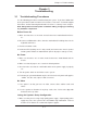
GLAN1
®
JLAN1
S
UPER X7DB8/E
GLAN2
Fan1
8-pin PWR
FP Ctrl
SPK
PW LED
JOH1
Fan3
IDE1
Floppy
BIOS
320 SCSI Channel A
Fan4
SATA1
SATA0
USB2/3
SMB
PCI-X 100 MHz ZCR
PCI-X 133 MHz
JWD
Battery
VGA
PCI-Exp x8
North Bridge
VGA
COM1
USB0/1
KB/
Mouse
Fan6
Fan5
ATX PWR
4-Pin
PWR
J3P
Parrallel
Port
24-Pin
JPG1
SCSI CTRL
CPU1
CPU2
South
Bridge
PXH
DIMM 1A (Bank 1)
Fan7
JAR
PSF
Fan2
Compact Flash
LE1
Fan8
JCF1
JWF1
JPA2
JPA3
JPA1
320 SCSI Channel B
SATA3
SATA2
SATA4
SATA5
JL1
JK1
Slot1
Slot2
Slot3
PCI-X 133 MHz
Slot4
JPL1
JPL2
Slot5
PCI-Exp x4
Slot6
PCI-Exp x8
SEPC
SIMLP IPMI
Slot7
DIMM 1B (Bank 1)
DIMM 2A (Bank 2)
DIMM 2B (Bank 2)
DIMM 3A (Bank 3)
DIMM 3B (Bank 3)
DIMM 4A (Bank 4)
DIMM 4B (Bank 4)
JBT1
USB4
JWOR
JCOM2
DA2
WOL
DA1
S I/O
JP1
LAN
CTRL
J27
J28
SGPIO1
SGPIO2
SMB PS
CTRL
J7
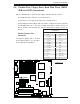
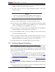
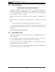
Floppy Connector
The fl oppy connector is located next
to the compact fl ash card slot. See
the table below for pin defi nitions.
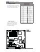
Floppy Drive Connector
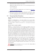
Pin Defi nitions (Floppy)
Pin# Defi nition Pin # Defi nition
1 Ground 2 FDHDIN
3 Ground 4 Reserved
5 Key 6 FDEDIN
7 Ground 8 Index
9 Ground 10 Motor Enable
11 Ground 12 Drive Select B
13 Ground 14 Drive Select B
15 Ground 16 Motor Enable
17 Ground 18 DIR
19 Ground 20 STEP
21 Ground 22 Write Data
23 Ground 24 Write Gate
25 Ground 26 Track 00
27 Ground 28 Write Protect
29 Ground 30 Read Data
31 Ground 32 Side 1 Select
33 Ground 34 Diskette
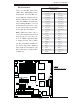
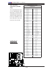
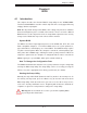
SIMLP IPMI Slot
There is a SIM Low Profile
IPMI Slot on the motherboard.
Refer to the layout below for
the IPMI Slot location.
A
B
A. Floppy
B. SIMLP IPMI