
Manual

2-14
SUPER P4SCT/P4SCT+/P4SCT+II User's Manual
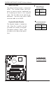
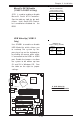
Ethernet Ports GLAN1 and
GLAN2 (*P4SCT/P4SCT+II
only)
Two Eth
ernet ports
(designated GLAN1 and
GLAN2) are located beside the
VGA port on the IO backplane.
These ports accept RJ45 type
cables.
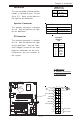
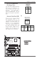
VGA Connector
A VGA connector (JG1) is
located next to the GLAN1 on
the IO backplane. Refer to the
board layout below for the
location.
SMB Header
A System Management Bus
header is located at J15. Connect
the appropriate cable here to uti-
lize SMB on your system.
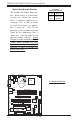
SMB Header
Pin Definitions (J15)
Pin
Number
1
2
3
4
Definition
Data
Ground
Clock
No Connection
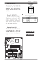
CPU
478 PGA
MCH
PWR LED
COM2
USB 1/2
P
a
r
a
l
l
e
l
P
o
r
t
JPWAKE
WOR
O
H
F
A
N
/
C
H
F
a
n
5
COM 1
VGA
GLAN 1
PCI 1-X
PCI-X 2
PCI -X 3
PCI 2
F
L
O
P
P
Y
BATTERY
BIOS
DIMM 0A (Blue)
Watch Dog
FRONT PANEL CTR
BANK0
BANK1
®
JF1
WOL
I
R
S
u
p
e
r
I
/
O
Speaker
I-SATA LED
Keylock
USB 3/4
24-pin ATX PWR Conn
S
U
P
E
R
P
4
S
C
T
/P
4
S
C
T
+
/P
4
S
C
T
+
II
GLAN 2
PCI 1
CHS FAN3
Intel's SATA2
KB/Mouse
JPUSB
L
A
N
2
E
n
a
b
le
RAGE-XL
+12V 4-pin PWR Conn.
PWR Froce On
(North Bridge)
CHS FAN4
C
P
U
S
p
e
e
d
C
P
U
/
C
H
F
a
n
1
Intel's SATA1
SATA1/5
SATA3/7SATA4/8
VGA Enable
AGP Pro
SMBus
SATA CTLR
GLAN CTLR
82541
CLR CMOS
Hance
Rapids
M-SATA1-2 Enable
Marvell
SATA2/6
I
D
E
1
I
D
E
2
Ch. Intru.
CHS FAN2
(Marvall's SATA)
Standby LED
LAN CTLR
82547
DIMM 1A (Blue)
DIMM 0B (Black)
DIMM 1B (Black)
Speaker
M- SATA LED
PWR Force On
B. GLAN1 & GLAN2
A. VGA Header
C. SMB Header
A
B
C