
Manual

2-18
SUPER P4SCT/P4SCT+/P4SCT+II User's Manual
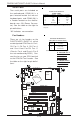
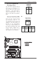
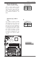
CMOS Clear
JBT1 is not actually a jumper but
consists of two contact pads. To
clear the contents of CMOS, short
these pads together by touching
them both with a metal conductor
such as the head of a small
screwdriver. Note: for ATX
power supplies, you must com-
pletely shut down the system and
remove the AC power cord before
clearing CMOS.
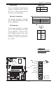
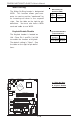
2-7 Jumper Settings
Explanation of
Jumpers
To modify the operation of the
motherboard, jumpers can be used
to choose between optional set-
tings. Jumpers create shorts be-
tween two pins to change the
function of the connector. Pin 1 is
identified with a square solder pad
on the printed circuit board. See
the motherboard layout pages for
jumper locations.
Note: On a two-pin jumper,
"Closed" means the jumper is on
both pins and "Open" means the
jumper is either on only one pin or
completely removed.
Connector
Pins
Jumper
Cap
Setting
Pin 1-2 short
3 2 1
3 2 1
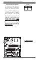
CPU
478 PGA
MCH
PWR LED
COM2
USB 1/2
P
a
r
a
l
l
e
l
P
o
r
t
JPWAKE
WOR
O
H
F
A
N
/
C
H
F
a
n
5
COM 1
VGA
GLAN 1
PCI 1-X
PCI-X 2
PCI -X 3
PCI 2
F
L
O
P
P
Y
BATTERY
BIOS
DIMM 0A (Blue)
Watch Dog
FRONT PANEL CTR
BANK0
BANK1
®
JF1
WOL
IR
S
u
p
e
r
I
/
O
Speaker
I-SATA LED
Keylock
USB 3/4
24-pin ATX PWR Conn
S
U
P
E
R
P
4
S
C
T
/
P
4
S
C
T
+
/
P
4
S
C
T
+
I
I
GLAN 2
PCI 1
CHS FAN3
Intel's SATA2
K
B
/
M
o
u
s
e
JPUSB
LAN2 Enable
RAGE-XL
+12V 4-pin PWR Conn.
PWR Froce On
(North Bridge)
CHS FAN4
CPU Speed
C
P
U
/
C
H
F
a
n
1
Intel's SATA1
SATA1/5
SATA3/7SATA4/8
VGA Enable
AGP Pro
SMBus
SATA CTLR
GLAN CTLR
82541
CLR CMOS
Hance
Rapids
M-SATA1-2 Enable
Marvell
SATA2/6
IDE1
IDE2
Ch. Intru.
CHS FAN2
(Marvall's SATA)
Standby LED
LAN CTLR
82547
DIMM 1A (Blue)
DIMM 0B (Black)
DIMM 1B (Black)
Speaker
M- SATA LED
PWR Force On
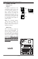
A. Clear CMOS
A