SUPER SUPERSERVER 5017C-MTF 5017C-MTRF USER’S MANUAL 1.
The information in this User’s Manual has been carefully reviewed and is believed to be accurate. The vendor assumes no responsibility for any inaccuracies that may be contained in this document, makes no commitment to update or to keep current the information in this manual, or to notify any person or organization of the updates. Please Note: For the most up-to-date version of this manual, please see our web site at www.supermicro.com. Super Micro Computer, Inc.
Preface Preface About This Manual This manual is written for professional system integrators and PC technicians. It provides information for the installation and use of the SuperServer 5017C-MTF/ 5017C-MTRF. Installation and maintenance should be performed by experienced technicians only. The SuperServer 5017C-MTF/5017C-MTRF is a high-end server based on the SC813MTQ-350B/SC813MTQ-R400B 1U rackmount chassis and the Super X9SCL-F single processor serverboard.
SUPERSERVER 5017C-MTF/5017C-MTRF User's Manual Chapter 4: System Safety You should thoroughly familiarize yourself with this chapter for a general overview of safety precautions that should be followed when installing and servicing the SuperServer 5017C-MTF/5017C-MTRF. Chapter 5: Advanced Serverboard Setup Chapter 5 provides detailed information on the X9SCL-F serverboard, including the locations and functions of connections, headers and jumpers.
Preface Notes v
SUPERSERVER 5017C-MTF/5017C-MTRF User's Manual Table of Contents Chapter 1 Introduction 1-1 Overview ......................................................................................................... 1-1 1-2 Motherboard Features ..................................................................................... 1-2 Processors ...................................................................................................... 1-2 Memory .........................................................
Table of Contents Chapter 3 System Interface 3-1 Overview ......................................................................................................... 3-1 3-2 Control Panel Buttons ..................................................................................... 3-1 Reset ............................................................................................................... 3-1 Power ................................................................................................
SUPERSERVER 5017C-MTF/5017C-MTRF User's Manual Supero Doctor III ........................................................................................... 5-24 Chapter 6 Advanced Chassis Setup 6-1 Static-Sensitive Devices .................................................................................. 6-1 Precautions ..................................................................................................... 6-1 Unpacking .......................................................................
Chapter 1: Introduction Chapter 1 Introduction 1-1 Overview The SuperServer 5017C-MTF/5017C-MTRF is a high-end server comprised of two main subsystems: the SC813MTQ-350B/SC813MTQ-R400B 1U server chassis and the X9SCL-F single processor motherboard. Please refer to our web site for information on operating systems that have been certified for use with the system (www.supermicro.com).
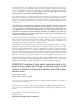
SUPERSERVER 5017C-MTF/5017C-MTRF User's Manual 1-2 Motherboard Features At the heart of the SuperServer 5017C-MTF/5017C-MTRF lies the X9SCL-F, a single processor motherboard based on Intel's C202 chipset. Below are the main features of the X9SCL-F (see Figure 1-1 for a block diagram of the chipset). Processors The X9SCL-F supports a single Intel® Xeon® E3-1200 Series processor or a Core TM i3-2100 Series processor in an LGA1155 socket.
Chapter 1: Introduction 1-3 Server Chassis Features The following is a general outline of the main features of the SC813MTQ chassis. System Power When configured as a SuperServer 5017C-MTF, the SC813MTQ chassis includes a single 350W power supply. When configured as a SuperServer 5017C-MTRF, the SC813MTQ chassis includes a redundant 400W power supply. SATA Subsystem For the 5017C-MTF/5017C-MTRF, the SC813MTQ chassis was designed to support four SATA hard drives, which are hot-swappable units.
SUPERSERVER 5017C-MTF/5017C-MTRF User's Manual Figure 1-1. Intel C200 Chipset: System Block Diagram Note: This is a general block diagram. Please see Chapter 5 for details. DIMM1 DIMM2(Far) 4 UDIMM DDR3 (CHA) PCIe x8 Slot (Slot 7) PCIe x8 Slot (Slot 6) PCIe2.0_x8 5.0Gb PCIe2.0_x8 5.0Gb 1333/1066MHz LGA 1155 Socket DDR3 (CHB) 1333/1066MHz CPU DIMM1 DIMM2(Far) SVID x4 DMI II 5.0Gb VRM 12 MISC VRs PCIe x8 Slot (Slot 4) PCIe_x4 5.0Gbps 6 SATA Ports SATA-II 300MB/s 9 USB Ports PCIe_x1 2.
Chapter 1: Introduction 1-4 Contacting Supermicro Headquarters Address: Super Micro Computer, Inc. 980 Rock Ave. San Jose, CA 95131 U.S.A. Tel: +1 (408) 503-8000 Fax: +1 (408) 503-8008 Email: marketing@supermicro.com (General Information) support@supermicro.com (Technical Support) Web Site: www.supermicro.com Europe Address: Super Micro Computer B.V. Het Sterrenbeeld 28, 5215 ML 's-Hertogenbosch, The Netherlands Tel: +31 (0) 73-6400390 Fax: +31 (0) 73-6416525 Email: sales@supermicro.
SUPERSERVER 5017C-MTF/5017C-MTRF User's Manual Notes 1-6
Chapter 2: Server Installation Chapter 2 Server Installation 2-1 Overview This chapter provides a quick setup checklist to get your SuperServer 5017CMTF/5017C-MTRF up and running. Following the steps in the order given should enable you to have the system operational within a minimal amount of time. This quick setup assumes that your 5017C-MTF/5017C-MTRF system has come to you with the processor and memory preinstalled.
SUPERSERVER 5017C-MTF/5017C-MTRF User's Manual installation only in a Restricted Access Location (dedicated equipment rooms, service closets and the like). • This product is not suitable for use with visual display work place devices acccording to §2 of the the German Ordinance for Work with Visual Display Units.
Chapter 2: Server Installation Rack Mounting Considerations Ambient Operating Temperature If installed in a closed or multi-unit rack assembly, the ambient operating temperature of the rack environment may be greater than the ambient temperature of the room. Therefore, consideration should be given to installing the equipment in an environment compatible with the manufacturer’s maximum rated ambient temperature (Tmra).
SUPERSERVER 5017C-MTF/5017C-MTRF User's Manual 2-4 Installing the System into a Rack This section provides information on installing the SuperServer 5017C-MTF/5017CMTRF into a rack unit with the rack rails provided. If the server has already been mounted into a rack, you can skip ahead to Sections 2-5 and 2-6. There are a variety of rack units on the market, which may mean the assembly procedure will differ slightly.
Chapter 2: Server Installation Figure 2-1. Installing Rear Inner Chassis Rails Installing the Rack Rails Determine where you want to place the SuperServer 5017C-MTF/5017C-MTRF in the rack (see Rack and Server Precautions in Section 2-3). Position the chassis rail guides at the desired location in the rack, keeping the sliding rail guide facing the inside of the rack. Screw the assembly securely to the rack using the brackets provided.
SUPERSERVER 5017C-MTF/5017C-MTRF User's Manual Installing the Server into the Rack You should now have rails attached to both the chassis and the rack unit. The next step is to install the server into the rack. Do this by lining up the rear of the chassis rails with the front of the rack rails. Slide the chassis rails into the rack rails, keeping the pressure even on both sides (you may have to depress the locking tabs when inserting). See Figure 2-2.
Chapter 2: Server Installation Installing the Server into a Telco Rack To install the SuperServer 5017C-MTF/5017C-MTRF into a Telco type rack, use two L-shaped brackets on either side of the chassis (four total). First, determine how far the server will extend out the front of the rack. Larger chassis should be positioned to balance the weight between front and back. If a bezel is included on your server, remove it.
SUPERSERVER 5017C-MTF/5017C-MTRF User's Manual 2-5 Checking the Motherboard Setup After you install the 5017C-MTF/5017C-MTRF in the rack, you will need to open the unit to make sure the motherboard is properly installed and all the connections have been made. Accessing the Inside of the System 1. Grasp the two handles on either side and pull the unit straight out until it locks (you will hear a "click"). 2. Depress the two buttons on the top of the chassis to release the top cover.
Chapter 2: Server Installation Figure 2-4. Accessing the Inside of the System Release buttons 2-6 Checking the Drive Bay Setup Next, you should check to make sure the peripheral drives and the SATA drives and their backplane have been properly installed and all essential connections have been made. Checking the Drives 1. The SATA disk drives can be installed and removed from the front of the chassis without removing the top chassis cover. 2.
SUPERSERVER 5017C-MTF/5017C-MTRF User's Manual Checking the Airflow 1. Airflow is provided by four high-performance 4-cm input fans. The system component layout was carefully designed to promote sufficient airflow through the small 1U rackmount space. 2. Also note that all power and data cables have been routed in such a way that they do not block the airflow generated by the fans. Providing Power 1.
Chapter 3: System Interface Chapter 3 System Interface 3-1 Overview There are several LEDs on the control panel as well as others on the hard drive carriers to keep you constantly informed of the overall status of the system as well as the activity and health of specific components. There are also two buttons on the chassis control panel and an on/off switch on the power supply. This chapter explains the meanings of all LED indicators and the appropriate response you may need to take.
SUPERSERVER 5017C-MTF/5017C-MTRF User's Manual 3-3 Control Panel LEDs The control panel located on the front of the SC813MTQ chassis has five LEDs. These LEDs provide you with critical information related to different parts of the system. This section explains what each LED indicates when illuminated and any corrective action you may need to take. Overheat/Fan Fail When this LED flashes, it indicates a fan failure.
Chapter 3: System Interface Power Indicates power is being supplied to the system's power supply units. This LED should normally be illuminated when the system is operating. 3-4 Hard Drive Carrier LEDs Each drive carrier has two LEDs. • • Green: When illuminated, the green LED on the drive carrier indicates drive activity. A connection to the backplane enables this LED to blink on and off when that particular drive is being accessed. Red: The red LED to indicate a drive failure.
SUPERSERVER 5017C-MTF/5017C-MTRF User's Manual Notes 3-4
Chapter 4: System Safety Chapter 4 System Safety 4-1 Electrical Safety Precautions ! Basic electrical safety precautions should be followed to protect yourself from harm and the SuperServer 5017C-MTF/5017C-MTRF from damage: • • • • • • • Be aware of the locations of the power on/off switch on the chassis as well as the room's emergency power-off switch, disconnection switch or electrical outlet. If an electrical accident occurs, you can then quickly remove power from the system.
SUPERSERVER 5017C-MTF/5017C-MTRF User's Manual • This product may be connected to an IT power system. In all cases, make sure that the unit is also reliably connected to Earth (ground). • Serverboard Battery: CAUTION - There is a danger of explosion if the onboard battery is installed upside down, which will reverse its polarites (see Figure 4-1). This battery must be replaced only with the same or an equivalent type recommended by the manufacturer (CR2032).
Chapter 4: System Safety • Remove any jewelry or metal objects from your body, which are excellent metal conductors that can create short circuits and harm you if they come into contact with printed circuit boards or areas where power is present. • After accessing the inside of the system, close the system back up and secure it to the rack unit with the retention screws after ensuring that all connections have been made.
SUPERSERVER 5017C-MTF/5017C-MTRF User's Manual 4-4 Operating Precautions ! Care must be taken to assure that the chassis cover is in place when the 5017CMTF/5017C-MTRF is operating to assure proper cooling. Out of warranty damage to the system can occur if this practice is not strictly followed. Figure 4-1. Installing the Onboard Battery LITHIUM BATTERY BATTERY HOLDER ! Please handle used batteries carefully.
Chapter 5: Advanced Motherboard Setup Chapter 5 Advanced Motherboard Setup This chapter covers the steps required to install processors and heatsinks to the X9SCL-F motherboard, connect the data and power cables and install add-on cards. All motherboard jumpers and connections are described and a layout and quick reference chart are included in this chapter. Remember to close the chassis completely when you have finished working on the motherboard to protect and cool the system sufficiently.
SUPERSERVER 5017C-MTF/5017C-MTRF User's Manual 5-2 Processor and Heatsink Installation Notes: • Always connect the power cord last and always remove it before adding, removing or changing any hardware components. Make sure that you install the processor into the CPU socket before you install the CPU heatsink. • If you buy a CPU separately, make sure that you use an Intel-certified multidirectional heatsink only.
Chapter 5: Advanced Motherboard Setup 3. Use your thumb and your index finger to hold the CPU at the top center edge and the bottom center edge of the CPU. 4. Align the CPU key (the semi-circle cutouts) against the socket keys. Once aligned, carefully lower the CPU straight down to the socket. (Do not drop the CPU on the socket. Do not move the CPU horizontally or vertically. Do not rub the CPU against the surface or against any pins of the socket to avoid damage to the CPU or the socket.
SUPERSERVER 5017C-MTF/5017C-MTRF User's Manual CPU properly installed Load lever locked into place. ! Warning: The CPU will only seat inside the socket in one direction. Make sure it is properly inserted before closing the load plate. If it doesn't close properly, do not force it as it may damage your CPU. Instead, open the load plate again and double-check that the CPU is aligned properly. Installing a Passive CPU Heatsink 1.
Chapter 5: Advanced Motherboard Setup Figure 5-3. Installing the Heatsink 3. Once the CPU is loose, remove the it from the CPU socket. 4. Clean the surface of the CPU and the heatsink, removing the used thermal grease. Reapply the proper amount of thermal grease on the surface before re-installing the CPU and the heatsink. Figure 5-4.
SUPERSERVER 5017C-MTF/5017C-MTRF User's Manual 5-3 Connecting Cables Now that the processors are installed, the next step is to connect the cables to the motherboard. These include the data (ribbon) cables for the peripherals and control panel and the power cables. Connecting Data Cables The cables used to transfer data from the peripheral devices have been carefully routed in preconfigured systems to prevent them from blocking the flow of cooling air that moves through the system from front to back.
Chapter 5: Advanced Motherboard Setup All JF1 wires have been bundled into single keyed ribbon cable to simplify their connection. Connect one end of this cable to JF1 and the other end to the Control Panel printed circuit board, located just behind the system status LEDs in the chassis. See the Connector Definitions section in this chapter for details and pin descriptions of JF1. Figure 5-1.
SUPERSERVER 5017C-MTF/5017C-MTRF User's Manual 5-5 Installing Memory Note: Check the Supermicro web site for recommended memory modules. CAUTION Exercise extreme care when installing or removing DIMM modules to prevent any possible damage. Installing DIMMs 1. Insert the desired number of DIMMs into the memory slots, starting with slots DIMM1A. Pay attention to the notch along the bottom of the module to prevent inserting the DIMM module incorrectly. See Figure 5-5. 2.
Chapter 5: Advanced Motherboard Setup Figure 5-3. Installing DIMM into Slot Notch Notch To Install: Insert module vertically and press down until it snaps into place. Pay attention to the alignment notch at the bottom. To Remove: Use your thumbs to gently push the release tabs near both ends of the module. This should release it from the slot. Front View Note: Notch should align with the receptive key point on the slot.
SUPERSERVER 5017C-MTF/5017C-MTRF User's Manual 5-6 Adding PCI Cards PCI Expansion Slots One riser card is used to support a PCI expansion (add-on) card in the system. The SC813MTQ-350B chassis can accommodate one standard size (full height full length) PCI expansion card. When viewed from the chassis front, the card installs to the left rear of the system. PCI Card Installation Before installing a PCI add-on card, make sure it is supported by the riser card.
Chapter 5: Advanced Motherboard Setup 5-7 Motherboard Details 47 1 46 1 45 1 44 1 JPI2C KB/MOUSE 11 IPMI _LAN USB/0/1 FP CTRL JPW1 JPUSB1 DIMM2B 42 1 FAN1 DIMM1B DDR3 1066/1333 UDIMM required PHY JWD 41 1 JSPK 40 1 DIMM2A COM1 12 13 14 15 JPW2 43 1 JF1 48 1 JLED1 Figure 5-4. SUPER X9SCL-F Layout JTPM DIMM1A SPKR1 39 1 S I/O VGA FAN2 38 1 Fan4 Socket H2 LGA 1155 CPU 82574L LAN1 PHY CPU LAN2 X9SCM/X9SCL(-F) Rev.1.0 82579 PHY JPL1 JPL2 JPB 37 1 Slot7 PCI-E 2.
SUPERSERVER 5017C-MTF/5017C-MTRF User's Manual Headers/Connectors Number Connector Description 21 B1 Onboard Battery 4,16 COM1/COM2 COM1/2 Serial Port/Header 35 BIOS SPI BIOS 42,38,37,7,30 Fans 1~4, Fan A System/CPU Fan Headers 36 J31 SPI Programming (internal use) 43 JF1 Front Panel Control Header 33 JL1 Chassis Intrusion Header 44 JLED1 Power LED Indicator Header 46 JPW1 24-pin ATX Main Power Connector 47 JPW2 +12V 8-pin CPU power Connector 1 KB/Mouse Keyboard/Mouse Con
Chapter 5: Advanced Motherboard Setup 5-8 Connector Definitions ATX Power 24-pin Connector Pin Definitions (JPW1) ATX Power Connector A 24-pin main power connector is located at JPW1. This power connector meet the SSI EPS 12V specification. See the table on the right for pin definitions. Pin# Definition Pin # Definition 13 +3.3V 1 +3.3V 14 -12V 2 +3.
SUPERSERVER 5017C-MTF/5017C-MTRF User's Manual NIC1/NIC2 (LAN1/LAN2) The NIC (Network Interface Controller) LED connection for LAN port 1 is located LAN1/LAN2 LED Pin Definitions (JF1) on pins 11 and 12 of JF1, and the LED connection for LAN Port 2 is on Pins 9 and 10. NIC1 LED and NIC2 LED are 2-pin NIC LED headers. Attach NIC LED cables to NIC1 LED and NIC2 LED to display network activities for LAN 1 and Pin# Definition 9/11 Vcc 10/12 LAN Act LAN2.
Chapter 5: Advanced Motherboard Setup Back Panel USB0/1 Pin Definitions Universal Serial Bus (USB) Pin# Definition Two Universal Serial Bus ports (USB 0/1) are located on the I/O backpanel and an additional six USB ports in three headers, USB2/3, 4/5, 12/13 provide front/ Pin# Definition 1 +5V 5 +5V 2 USB_PN1 6 USB_PN0 3 USB_PP1 7 USB_PP0 4 Ground 8 Ground back chassis access. USB 11 is a Type A USB connector.
SUPERSERVER 5017C-MTF/5017C-MTRF User's Manual Fan Headers The X9SCL-F has five fan headers (Fan1 ~ Fan4 and FanA). These are all 4-pin fan headers, however pins 1-3 are backward Fan Header Pin Definitions compatible with traditional 3-pin fans. A fan speed control setting in the BIOS (Hardware Monitoring section) allows the BIOS to automatically set fan speeds based on the system temperature. Refer to the table on the right for pin definitions. Pin# Definition 1 Ground (Black) 2 2.
Chapter 5: Advanced Motherboard Setup Trusted Platform Module Header This header is used to connect a Trusted Platform Module (TPM), available sepa- Trusted Platform Module Header Pin Definitions Pin # Definition Pin # Definition 1 LCLK 2 GND 3 LFRAME 4 No Pin and authentication of hard drives, disallowing access if the TPM associated with 5 LRESET 6 VCC5 7 LAD3 8 LAD2 it is not installed in the system. See the 9 VCC3 10 LAD1 table on the right for pin definitions.
SUPERSERVER 5017C-MTF/5017C-MTRF User's Manual T-SGPIO 0/1 Headers Two T-SGPIO (Serial-Link General Purpose Input/Output) headers are located near the SATA connectors on the motherboard. These headers are used to communicate with the enclosure management chip in the system. See the table on Serial_Link-SGPIO Pin Definitions Pin# Definition Pin Definition 1 NC 2 NC 3 Ground 4 DATA Out 5 Load 6 Ground 7 Clock 8 NC the right for pin definitions.
Chapter 5: Advanced Motherboard Setup 5-9 Jumper Settings Explanation of Jumpers To modify the operation of the motherboard, jumpers can be used to choose between optional settings. Jumpers cre- 3 2 1 3 2 1 Connector Pins ate shorts between two pins to change the function of the connector. Pin 1 is identified with a square solder pad on the Jumper printed circuit board. See the diagram at right for an example of jumping pins 1 and Setting 2.
SUPERSERVER 5017C-MTF/5017C-MTRF User's Manual PCI Slot SMB Enable PCI Slot SMB Enable/Disable Jumper Settings Use Jumpers JI2C1/JI2C2 to enable PCI SMB (System Management Bus) support to improve system management for the PCI slots. Default is disabled. See the Jumper Setting Definition Closed Enabled Open (Default) Disabled table on the right for jumper settings. LAN Port Enable/Disable Use JPL1/JPL2 to enable or disable LAN Ports 1 and 2 on the motherboard.
Chapter 5: Advanced Motherboard Setup 5-10 Onboard Indicators LAN1/LAN2 LEDs LAN LED Connection Speed Indicator The Ethernet ports (located beside the VGA port) have two LEDs. On each Giga- LED State Definition bit LAN port, the yellow LED indicates Off No connection or 10 Mb/s activity when blinking while the other LED Green 100 Mb/s may be green, amber or off to indicate the speed of the connection.
SUPERSERVER 5017C-MTF/5017C-MTRF User's Manual 5-11 SATA Drive Connections SATA Port Pin Definitions (SATA0 ~ SATA5) Pin # Definition 1 Ground Six Serial ATA (SATA) ports (I-SATA 0~5) are located on the motherboard. See the 2 TXP 3 TXN table on the right for pin definitions for the 4 Ground onboard SATA ports.
Chapter 5: Advanced Motherboard Setup 5-12 Installing Drivers After all the hardware and operating system have been installed, you need to install certain drivers. The necessary drivers are all included on the Supermicro CD that came packaged with your motherboard. After inserting this CD into your CD-ROM drive, the display shown in Figure 5-4 should appear. (If this display does not appear, click on the My Computer icon and then on the icon representing your CD-ROM drive.
SUPERSERVER 5017C-MTF/5017C-MTRF User's Manual SuperDoctor III The SuperDoctor® III program is a Web base management tool that supports remote management capability. It includes Remote and Local Management tools. The local management is called SD III Client. The SuperDoctor III program included on the CD-ROM that came with your motherboard allows you to monitor the environment and operations of your system.
Chapter 5: Advanced Motherboard Setup SuperDoctor III Interface Display Screen (Remote Control) Note: The SuperDoctor III program and User's Manual can be downloaded from the Supermicro web site at http://www.supermicro.com/products/accessories/software/ SuperDoctorIII.cfm. For Linux, we recommend using SuperDoctor II.
SUPERSERVER 5017C-MTF/5017C-MTRF User's Manual Notes 5-26
Chapter 6: Advanced Chassis Setup Chapter 6 Advanced Chassis Setup This chapter covers the steps required to install components and perform maintenance on the SC813MTQ chassis. For component installation, follow the steps in the order given to eliminate the most common problems encountered. If some steps are unnecessary, skip ahead to the step that follows. Tools Required: The only tool you will need to install components and perform maintainance is a Philips screwdriver.
SUPERSERVER 5017C-MTF/5017C-MTRF User's Manual Figure 6-1. Chassis Front View USB Ports COM2 Port Control Panel SATA Drives (4) Figure 6-2. Chassis Rear View Power Supply* PCI Expansion Slot Dedicated IPMI Port Mouse Port Keyboard Port USB Ports COM1 Port VGA Port Ethernet Ports *The 5017C-MTRF includes two power supplies for redundancy.
Chapter 6: Advanced Chassis Setup 6-3 System Fans Four 4-cm high-performance fans provide the cooling for the SuperServer 5017CMTF/5017C-MTRF. The chassis includes air seals under the fans and at the chassis cross section, which separates the drive bay area from the serverboard area of the chassis to promote better airflow. It is highly important that the air seal is properly installed and making a good seal in order for the cooling air to circulate properly through the chassis.
SUPERSERVER 5017C-MTF/5017C-MTRF User's Manual Accessing the Drive Bays SATA Drives: Because of their hotswap capability, you do not need to access the inside of the chassis or power down the system to install or replace SATA drives. Proceed to the next step for instructions. Note: The operating system you use must have RAID support to enable the hot-swap capability of the drives.
Chapter 6: Advanced Chassis Setup Figure 6-4. Mounting a Drive in a Carrier SATA Backplane The SATA drives plug into a backplane that provides power, drive ID and bus termination. A RAID controller can be used with the backplane to provide data security for the drives. The backplane is already preconfigured, so there are no jumpers or switches present on it. Figure 6-5.
SUPERSERVER 5017C-MTF/5017C-MTRF User's Manual DVD-ROM Drive Installation The top cover of the chassis must be opened to gain full access to the DVD-ROM drive bay. The 5017C-MTF/5017C-MTRF accomodates only slim DVD-ROM drives. Side mounting brackets are needed to mount a slim DVD-ROM drive into the 5017CMTF/5017C-MTRF server.You must power down the system before installing or removing a DVD-ROM drive.
Chapter 6: Advanced Chassis Setup 6-5 Power Supply The SuperServer 5017C-MTF has a single 350 watt power supply. This power supply has the capability of operating at 100 - 240 input volts. Depress the main power button on the front of the chassis and then unplug the AC power cord to completely remove power from the system before removing the power supply. Power Supply Failure If the power supply unit fails, the system will shut down and you will need to replace the power supply unit.
SUPERSERVER 5017C-MTF/5017C-MTRF User's Manual The SuperServer 5017C-MTRF has a 400 watt redundant power supply consisting of two power modules. Each power supply module has an auto-switching capability, which enables it to automatically sense and operate at a 100V - 240V input voltage. If either of the two power supply modules fail, the other module will take the full load and allow the system to continue operation without interruption.
Chapter 7: BIOS Chapter 7 BIOS 7-1 Introduction This chapter describes the AMI BIOS Setup Utility for the X9SCL-F. The AMI ROM BIOS is stored in a Flash EEPROM and can be easily updated. This chapter describes the basic navigation of the AMI BIOS Setup Utility setup screens. Note: For instructions on BIOS recovery, please refer to the instruction guide posted at http://www.supermicro.com/support/manuals/.
SUPERSERVER 5017C-MTF/5017C-MTRF User's Manual How to Start the Setup Utility Normally, the only visible Power-On Self-Test (POST) routine is the memory test. As the memory is being tested, press the key to enter the main menu of the AMI BIOS Setup Utility. From the main menu, you can access the other setup screens. An AMI BIOS identification string is displayed at the left bottom corner of the screen, below the copyright message.
Chapter 7: BIOS System Overview: The following BIOS information will be displayed: System Time/System Date Use this option to change the system time and date. Highlight System Time or System Date using the arrow keys. Enter new values through the keyboard. Press the key or the arrow keys to move between fields. The date must be entered in Day MM/DD/YY format. The time is entered in HH:MM:SS format. (Note: The time is in the 24-hour format. For example, 5:30 P.M. appears as 17:30:00.
SUPERSERVER 5017C-MTF/5017C-MTRF User's Manual 7-3 Advanced Setup Configurations Use the arrow keys to select Boot Setup and hit to access the submenu items: BIOS SETUP UTILTY Main Advanced Event Logs IPMI Boot Security Exit System Boot Feature Setting.
Chapter 7: BIOS 19 at boot and allow the drives that are attached to these host adaptors to function as bootable disks. If this item is set to Disabled, the ROM BIOS of the host adaptors will not capture Interrupt 19, and the drives attached to these adaptors will not function as bootable devices. The options are Enabled and Disabled. Watch Dog Function If enabled, the Watch Dog Timer will allow the system to reboot when it is inactive for more than 5 minutes. The options are Enabled and Disabled.
SUPERSERVER 5017C-MTF/5017C-MTRF User's Manual Adjacent Cache Line Prefetch (Available when supported by the CPU) The CPU fetches the cache line for 64 bytes if this option is set to Disabled. The CPU fetches both cache lines for 128 bytes as comprised if Enabled.
Chapter 7: BIOS P-STATE Coordination This feature selects the type of coordination for the P-State of the processor. P-State is a processor operational state that reduces the processor's voltage and frequency. This makes the processor more energy effiicient, resulting in further gains. The options are HW_ALL, SW_ALL and SW-ANY. CPU C3 Report, CPU C6 Report This BIOS feature enables or disables C3 (ACPI C2) or C6 (ACPI C3) reporting to the operating system. The options are Disabled and Enabled.
SUPERSERVER 5017C-MTF/5017C-MTRF User's Manual North Bridge Configuration This item displays the current North Bridge Revision. VT-d Select Enabled to enable Intel's Virtualization Technology support for Direct I/O VT-d by reporting the I/O device assignments to VMM through the DMAR ACPI Tables. This feature offers fully-protected I/O resourcesharing across the Intel platforms, providing the user with greater reliability, security and availability in networking and data-sharing.
Chapter 7: BIOS Wake on LAN from S5 Select Enabled to enable the capabiltiy to 'wake-up' the system from the S5 power state (Soft Off State) through the Ethernet controller. The settings are Enabled and Disabled. Legacy USB Support This feature enables support for legacy USB devices. Select Auto to disable legacy support if USB devices are not present. Select Disable to have USB devices available only for EFI applicatioins. The options are Enabled, Disabled and Auto.
SUPERSERVER 5017C-MTF/5017C-MTRF User's Manual Aggressive Link Power Management This feature Enables or Disables Agressive Link Power Management support for Cougar Point B0 stepping and later. The options are Enabled and Disabled. SATA Port0~Port5 This item displays the information detected on the installed SATA drives on the particular SATA port. Staggered Spin Up Set this item to Enabled to enable Staggered Spin-up support. The options are Enabled and Disabled.
Chapter 7: BIOS PCI Latency Timer This feature sets the latency Timer of each PCI device installed on a PCI bus. Select 64 to set the PCI latency to 64 PCI clock cycles. The options are 32, 64, 96, 128, 160, 192, 224 and 248. SR-IOV Support Single Root I/O Virtualization (SR-IOV) is a specification that allows a PCIe device to appear as multiple physical devices to the system. The options are Disabled and Enabled. PCI-E Slot 4, 5, 6, & 7 OPROM Use this feature to enable or disable PCI slot Option ROMs.
SUPERSERVER 5017C-MTF/5017C-MTRF User's Manual Serial Port 2 Mode Use this feature to configure Serial Port 2 mode. The options are Normal, IrDA and ASK IR. IrDA (Infrared Data) is an industry standard for remote control devices. ASK IR (Amplitude Shifted Keying Infrared) is a protocol compatible with Sharp® branded PDAs and other infrared devices. Remote Access Configuration COM0/COM1/SOL Console Redirection Use this feature to enable console redirection for COM0 and COM1 ports.
Chapter 7: BIOS Parity: None, Even, Odd, Mark, or Space Stop Bits: 1 or 2 Hardware Health Configuration Fan Speed Control Mode This feature allows the user to decide how the system controls the speeds of the onboard fans. The CPU temperature and the fan speed are correlative. When the CPU on-die temperature increases, the fan speed will also increase for effective system cooling.
SUPERSERVER 5017C-MTF/5017C-MTRF User's Manual High – The processor is running hot. This is a ‘caution’ level since the CPU’s ‘Temperature Tolerance’ has been reached (or has been exceeded) and may activate an overheat alarm: The information provided above is for your reference only. For more information on thermal management, please refer to Intel’s Web site at www.Intel.com. Fan1 ~ Fan4, FanA Reading This feature displays the fan speed readings from fan interfaces Fan1 through Fan4 and FanA.
Chapter 7: BIOS 7-4 Event Logs BIOS SETUP UTILTY Main Advanced Event Logs IPMI Boot Security Exit Change Smbios Event Log Settings Press to change the Smbios Event Log configuration. View Smbios Event Log View System Event Log : : Enter: +/- : F1 : F2 : F3 : F4 : ESC : Select Screen Select Item Select Change Opt. General Help Previous Values Optimized Defaults Save & Exit Exit Version x.xx.xxxx. Copyright (C) 2010 American Megatrends, Inc.
SUPERSERVER 5017C-MTF/5017C-MTRF User's Manual 7-5 IPMI Configuration Intelligent Platform Management Interface (IPMI) is a set of common interfaces that IT administrators can use to monitor system health and to manage the system as a whole. For more information on the IPMI specifications, please visit Intel's website at www.intel.com.
Chapter 7: BIOS SEL Components - Change this item to enable or disable all features of System Event Logging. The options are Enabled and Disabled. When Enabled, the following can be configured: Erase SEL - This option erases all logged SEL events. The options are No, Yes, On Next reset and Yes, On Every reset. When SEL Full This option automatically clears the System Event Log memory of all messages when it is full. The options are Do Nothing and Erase Immediately.
SUPERSERVER 5017C-MTF/5017C-MTRF User's Manual 7-6 Boot Settings BIOS SETUP UTILTY Main Advanced Event Logs Setup Prompt Timeout IPMI Boot Security Exit 1 Number of seconds to wait for setup activation key. 65535 (0xFFFF) means indefinite waiting. Boot Options Priority : : Enter: +/- : F1 : F2 : F3 : F4 : ESC : Select Screen Select Item Select Change Opt. General Help Previous Values Optimized Defaults Save & Exit Exit Version x.xx.xxxx. Copyright (C) 2010 American Megatrends, Inc.
Chapter 7: BIOS 7-7 Security Settings BIOS SETUP UTILTY Main Advanced Event Logs IPMI Boot Security Exit Password Description Set Setup Administrator Pasword. If ONLY the administrator’s password is set, then this only limits access to Setup and is only asked for when entering Setup. If ONLY the User’s password is set, then this is a power on password and must be entered to boot or enter Setup. In Setup the User will have Administrator rights. The password must be 3 to 20 characters long.
SUPERSERVER 5017C-MTF/5017C-MTRF User's Manual 7-8 Exit Options BIOS SETUP UTILTY Main Advanced Event Logs IPMI Boot Security Exit Save Changes and Exit Discard Changes and Exit Discard Changes Exit system setup after saving the changes. Restore Defaults Save as User Defaults Restore User Defaults Boot Override Built-in EFI Shell : : Enter: +/- : F1 : F2 : F3 : F4 : ESC : Select Screen Select Item Select Change Opt.
Chapter 7: BIOS Save As User Defaults To set this feature, select Save as User Defaults from the Exit menu and press . This enables the user to save any changes to the BIOS setup for future use Restore User Defaults To set this feature, select Restore User Defaults from the Exit menu and press . Use this feature to retrieve user-defined settings that were saved previously. Boot Override Set this feature to override a previously defined boot device. The available devices will be listed below.
SUPERSERVER 5017C-MTF/5017C-MTRF User's Manual Notes 7-22
Appendix A: POST Error Beep Codes Appendix A BIOS Error Beep Codes During the POST (Power-On Self-Test) routines, which are performed each time the system is powered on, errors may occur. Non-fatal errors are those which, in most cases, allow the system to continue with bootup. The error messages normally appear on the screen. Fatal errors will not allow the system to continue to bootup. If a fatal error occurs, you should consult with your system manufacturer for possible repairs.
SUPERSERVER 5017C-MTF/5017C-MTRF User's Manual Notes A-2
Appendix B: System Specifications Appendix B System Specifications Processors Single Intel® Xeon® E3-1200 Series processor or a CoreTM i3-2100 Series processor in an LGA1155 socket Note: Please refer to our web site for a complete listing of supported processors. Chipset Intel C202 BIOS 64 Mb SPI AMI® Flash Memory Capacity Four DIMM sockets supporting up to 32 GB of unbuffered DDR3-1333/1066 memory See the memory section in Chapter 5 for details.
SUPERSERVER 5017C-MTF/5017C-MTRF User's Manual Weight Gross Weight: 38 lbs. (17.3 kg.) System Cooling Four 4-cm high performance fans System Input Requirements AC Input Voltage: 100-240V AC auto-range Rated Input Current: 4.2A (100V) to 1.8A (240V) Rated Input Frequency: 50 to 60 Hz Power Supply 5017C-MTF: Rated Output Power: 350W (Part# PWS-351-1H) Rated Output Voltages: +3.3V (15A), +5V (18A), +12V (29A), -12V (.
Appendix B: System Specifications Regulatory Compliance Electromagnetic Emissions: FCC Class A, EN 55022 Class A, EN 61000-3-2/-3-3, CISPR 22 Class A Electromagnetic Immunity: EN 55024/CISPR 24, (EN 61000-4-2, EN 61000-4-3, EN 61000-4-4, EN 61000-4-5, EN 61000-4-6, EN 61000-4-8, EN 61000-4-11) Safety: EN 60950/IEC 60950-Compliant, UL Listed (USA), CUL Listed (Canada), TUV Certified (Germany), CE Marking (Europe) California Best Management Practices Regulations for Perchlorate Materials: This Perchlorate w
SUPERSERVER 5017C-MTF/5017C-MTRF User's Manual Notes B-4