C2SBA+II C2SBA+ C2SBA C2SBE USER’S MANUAL Revision 1.
The information in this User’s Manual has been carefully reviewed and is believed to be accurate. The vendor assumes no responsibility for any inaccuracies that may be contained in this document, makes no commitment to update or to keep current the information in this manual, or to notify any person or organization of the updates. Please Note: For the most up-to-date version of this manual, please see our web site at www.supermicro.com. Super Micro Computer, Inc.
Preface About This Manual Preface This manual is written for system integrators, PC technicians and knowledgeable PC users. It provides information for the installation and use of the C2SBA+II/C2SBA+/C2SBA/C2SBE motherboard. The C2SBA+II/C2SBA+/ C2SBA/C2SBE supports single Intel Xeon 3000 Series/Core 2 Quad/Core 2 Duo Processor with a system bus speed of up to 1.33 GHz.
C2SBA+II/C2SBA+/C2SBA/C2SBE User’s Manual Table of Contents About This Manual ....................................................................................................... iii Manual Organization ..................................................................................................... iii Conventions Used in the Manual................................................................................... iii Chapter 1: Introduction 1-1 Overview . ........................................
Table of Contents Chassis Intrusion .................................................................................... 2-14 Fan Headers.............................................................................................. 2-15 VGA Connector......................................................................................... 2-15 ATX PS/2 Keyboard and PS/2 Mouse Ports............................................. 2-16 Serial Ports..................................................................
C2SBA+II/C2SBA+/C2SBA/C2SBE User’s Manual 3-2 Technical Support Procedures ........................................................................ 3-2 3-3 Frequently Asked Questions ........................................................................... 3-3 3-4 Returning Merchandise for Service.................................................................. 3-5 Chapter 4: BIOS 4-1 Introduction......................................................................................................
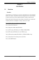
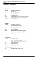
Chapter 1: Introduction Chapter 1 Introduction 1-1 Overview Checklist Congratulations on purchasing your computer motherboard from an acknowledged leader in the industry. Super Micro boards are designed with the utmost attention to detail to provide you with the highest standards in quality and performance. Please check that the following items have all been included with your motherboard. If anything listed here is damaged or missing, contact your retailer.
C2SBA+II/C2SBA+/C2SBA/C2SBE User’s Manual Contacting Super Micro Headquarters Address: Tel: Fax: Email: Web Site: Super Micro Computer, Inc. 980 Rock Ave. San Jose, CA 95131 U.S.A. +1 (408) 503-8000 +1 (408) 503-8008 marketing@supermicro.com (General Information) support@supermicro.com (Technical Support) www.supermicro.com Europe Address: Tel: Fax: Email: Super Micro Computer B.V.
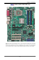
Chapter 1: Introduction C2SBA+II/C2SBA+/C2SBA/C2SBE Image Note: All pictures and drawings shown in this manual were based upon the latest PCB revision available at the time of publishing of the manual. The motherboard you've received may or may not look exactly the same as those in this manual.
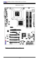
C2SBA+II/C2SBA+/C2SBA/C2SBE User’s Manual Motherboard Layout CPU Fan FAN1 4-Pin PWR FAN2 S I/O W83627DHG J28 Parallel Port COM1 Processor VGA J31 DIMM2A DIMM1B DIMM1A J40 LAN JPUSB1 Intel G33 USB 1/2 USB 3/4/5/6 J43 DIMM2B J30 JG1 24-pin ATX PWR KB/MOUSE J41 JKB Audio Fan5 Floppy J11 DIMM4 J1 Slot7 PCI-E x1 DIMM3 DIMM1 DIMM2 North Bridge J46 J27 J7 Slot6 PCI-E x16 Slot5 PCI-E x4 JBT1 J8 Battery I-SATA0 I-SATA4 I-SATA1 I-SATA5 JF1 LE1 FP USB 9/10 PCI2 FP USB 7
Chapter 1: Introduction C2SBA+II/C2SBA+/C2SBA/C2SBE Quick Reference Jumpers JBT1 JKB JI2C1/JI2C2 JP2 JP3 JP5 JPL1 JPUSB1 JPUSB2 JWD Description Default Setting CMOS Clear (See Chapter 2) Keyboard Enabled Pins 1-2 (Enabled) SMB to PCI Slots Open/Open (Disabled) ITE IDE Enabled Pins 1-2 (Enabled) (See Note 4) TPM Enabled Pins 1-2 (Enabled) (See Note 6) Audio Enabled Pins 1-2 (Enabled) Giga-bit LAN Enab.
C2SBA+II/C2SBA+/C2SBA/C2SBE User’s Manual Important Notes to the User • 1. Jumpers not indicated are for testing only. • 2. See Chapter 2 for detailed information on CPU/Heatsink installation, memory population, jumpers, connectors, I/O ports and JF1 front panel connections. • 3. " " indicates the location of "Pin 1.' • 4. IDE is available on the C2SBA/C2SBA+/C2SBA+II only. • 5. PCI Slot 4 is not available on the C2SBA+/C2SBA+II. • 6.
Chapter 1: Introduction Motherboard Features CPU • Single Intel Xeon 3000 Series/Core 2 Quad/Core 2 Duo Processor with a system bus speed of 1.33 GHz/1.
C2SBA+II/C2SBA+/C2SBA/C2SBE User’s Manual Onboard I/O • Built in ICH9 SATA Controller, 4 connectors for 4 devices (For the C2SBA+/ C2SBA/C2SBE) • Built in ICH9R SATA Controller, 6 connectors for 6 devices (For the C2SBA+II) • 1 floppy port interface (up to 2.88 MB) • 1 Fast UART 16550 compatible serial port/header • Intel 82566 Gigabit Ethernet Controller • PS/2 mouse and PS/2 keyboard ports • ITE-8212 IDE controller or ITE-8211 IDE controller (for PCB Rev. 1.
Chapter 1: Introduction VRM 11.0 VRM 11.0 LGA775_PROCESSOR CTRL DATA CTRL DATA 1 PCIE_x16 ADDR INTEGRATED GRAPHICS ADDR FSB: 1333/1066MHz G33/P35 GMCH/MCH PCIE_x16 CK505 CLK DDR2 800/667 DIMM_CHA DIMM_CHB GRAPHIC DMI 4 or 6 SATAII PORTS 12x USB2.0 PORTS PCIE_x1 S-ATA/300 PCIE_x4 ICH-9(R) USB2.0/1.1 PCI_32 PCI_32 W83627DHG LPC I/O KB. MS. FDD. HD-A TPM LPC LPC SPI BIOS PCIE_x1 7.1-CH HD_AUDIO SER.
C2SBA+II/C2SBA+/C2SBA/C2SBE User’s Manual 1-2 Chipset Overview The Intel G33/P35 chipset is specially designed for use with the Intel dual core processors. It consists of two primary components: the Graphic Memory Controller Hub (GMCH) and the I/O Controller Hub (ICH9/ICH9R). The GMCH (North Bridge) manages the data flow between the CPU interface (FSB), the System Memory interface, the External Graphics interface, and the I/O Controller through the DMI (Direct Media) Interface.
Chapter 1: Introduction 1-3 Recovery from AC Power Loss BIOS provides a setting for you to determine how the system will respond when AC power is lost and then restored to the system. You can choose for the system to remain powered off (in which case you must hit the power switch to turn it back on) or for it to automatically return to a power on state. See the Power Lost Control setting in the BIOS chapter of this manual to change this setting. The default setting is Last State.
C2SBA+II/C2SBA+/C2SBA/C2SBE User’s Manual enhance clock control. A hardware-based component provides software-independent thermal management that is compatible with the ACPI Revision 3.0a. Slow Blinking LED for Suspend-State Indicator When the CPU goes into a suspend state, the chassis power LED will start blinking to indicate that the CPU is in suspend mode. When the user presses any key, the CPU will wake-up and the LED will automatically stop blinking and remain on.
Chapter 1: Introduction 1-7 Versatile Media Capabilities High Definition Audio The High Definition Audio Controller embedded in the ICH9/ICH9R delivers up to 4 codecs that can be used for different types of codecs, such as audio and modem codecs. Operating at 3.3V or 1.5V, the embedded Audio Controller supports a multi-channel audio stream, 32-bit sample depth, up to 192 kHz of same rate, and can be used with a variety of microphones for input.
C2SBA+II/C2SBA+/C2SBA/C2SBE User’s Manual Notes 1-14
Chapter 2: Installation 2-1 Chapter 2 Installation Static-Sensitive Devices Electro-Static-Discharge (ESD) can damage electronic components. To prevent damage to your system board, it is important to handle it very carefully. The following measures are generally sufficient to protect your equipment from ESD. Precautions • Use a grounded wrist strap designed to prevent static discharge. Touch a grounded metal object before removing the board from the antistatic bag.
C2SBA+II/C2SBA+/C2SBA/C2SBE User's Manual 2-3 Processor and Heatsink Fan Installation ! When handling the processor package, avoid placing direct pressure on the label area of the fan. Notes: 1. Always connect the power cord last and always remove it before adding, removing or changing any hardware components. Make sure that you install the processor into the CPU LGA 775 socket before you install the CPU heatsink. 2.
Chapter 2: Installation 3. Use your thumb and your index finger to hold the CPU at the North Center Edge and the South Center Edge of the CPU. North Center Edge 4. Align CPU Pin1 (the CPU corner marked with a triangle) against the socket corner that is marked with a triangle cutout. 5. Align the CPU key that is the semi-circle cutout below a golden dot against the socket key, the Notch on the same side of the triangle cutout on the socket. 6.
C2SBA+II/C2SBA+/C2SBA/C2SBE User's Manual Installation of the Heatsink 1. Locate the CPU Fan on the motherboard. (Refer to the layout on the right for the CPU Fan location.) 2. Position the heatsink in such a way that the heatsink fan wires are closest to the CPU fan and are not interfered with other components. 3. Inspect the CPU Fan wires to make sure that the wires are routed through the bottom of the heatsink. 4. Remove the thin layer of the protective film from the copper core of the heatsink.
Chapter 2: Installation 8. Repeat Step 6 to insert all four heatsink fasteners into the mounting holes. 9. Once all four fasteners are securely inserted into the mounting holes and the heatsink is properly installed on the motherboard, connect the heatsink fan wires to the CPU Fan connector. Heatsink Removal 1. Unplug the power cord from the power supply. 2. Disconnect the heatsink fan wires from the CPU fan header. 3.
C2SBA+II/C2SBA+/C2SBA/C2SBE User's Manual 2-4 Installing DIMMs Note: Check the Super Micro web site for recommended memory modules. CAUTION Exercise extreme care when installing or removing DIMM modules to prevent any possible damage. Also note that the memory is interleaved to improve performance (See step 1). DIMM Installation 1. Insert the desired number of DIMMs into the memory slots, starting with DIMM1A.
Chapter 2: Installation Possible System Memory Allocation & Availability System Device Size Physical Memory Remaining (-Available) (4 GB Total System Memory) Firmware Hub flash memory (System BIOS) 1 MB 3.99 Local APIC 4 KB 3.99 Area Reserved for the chipset 2 MB 3.99 I/O APIC (4 Kbytes) 4 KB 3.99 PCI Enumeration Area 1 256 MB 3.76 PCI Express (256 MB) 256 MB 3.51 PCI Enumeration Area 2 (if needed) -Aligned on 256-MB boundary- 512 MB 3.01 VGA Memory 16 MB 2.85 TSEG 1 MB 2.
C2SBA+II/C2SBA+/C2SBA/C2SBE User's Manual 2-5 Control Panel Connectors/IO Ports The I/O ports are color coded in conformance with the PC 99 specification. See the graphics below for the colors and locations of the various I/O ports. Back Panel Connectors/IO Ports 8 4 C2SBA 2 1 3 7 18 14 17 11 6 10 13 16 5 9 12 15 Back Panel I/O Port Locations and Definitions Back Panel Connectors 1. Keyboard (Purple) 2. PS/2 Mouse (Green) 3. COM Port 1 (Turquoise) 4. Parallel Port (Printer) 5.
Chapter 2: Installation Front Control Panel JF1 contains header pins for various buttons and indicators that are normally located on a control panel at the front of the chassis. These connectors are designed specifically for use with Super Micro server chassis. See the pictures below for the descriptions of the various control panel buttons and LED indicators. Refer to the following section for descriptions and pin definitions.
C2SBA+II/C2SBA+/C2SBA/C2SBE User's Manual Front Control Panel Pin Definitions Power LED Power LED Pin Definitions The Power LED connection is located on pins 15 and 16 of JF1. Refer to the table on the right for pin definitions. Pin# Definition 15 LED_Anode+ 16 PWR LED Signal HDD LED HDD LED Pin Definitions LED_Anode+ 14 HD Active FAN2 DIMM2B DIMM2A DIMM1B DIMM1A A. PWR LED B.
Chapter 2: Installation NIC1 Indicator GLAN1/2 LED Pin Definitions The NIC (Network Interface Controller) LED connection for the GLAN port is located on pins 11 and 12 of JF1. Attach the NIC LED cables to display network activity. Refer to the table on the right for pin definitions.
C2SBA+II/C2SBA+/C2SBA/C2SBE User's Manual Reset Button Reset Button Pin Definitions The Reset Button connection is located on pins 3 and 4 of JF1. Attach it to a hardware reset switch on the computer case. Refer to the table on the right for pin definitions. Pin# Definition 3 Reset 4 Ground Power Button Definition 1 Power On 2 Ground COM1 A. Reset 24-pin ATX PWR DIMM1A DIMM2A DIMM1B DIMM2B VGA Parallel Port B.
Chapter 2: Installation 2-6 Connecting Cables ATX Power 24-pin Connector Pin Definitions ATX Main Power Connector A 24-pin main power connector is located at J40. This power connector meets the SSI EPS 12V specification. See the table on the right for pin definitions. 4-pin CPU Power Connector B 1 +3.3V 14 -12V 2 +3.
C2SBA+II/C2SBA+/C2SBA/C2SBE User's Manual Universal Serial Bus (USB) Back Panel USB (1-6) Pin Definitions There are 12 USB 2.0 (Universal Serial Bus) ports/headers on the motherboard. Six of them are Back Panel USB ports: USB#1/2 (J11) and USB#3/4/5/6 (J43). USB #7/8 (J44) and USB#9/10 (J45) are headers that can be used for front panel connections. Additionally, USB#11(J47) and USB#12 (J48) are onboard USB connectors that can be accessed from the front side of the chassis.
Chapter 2: Installation Fan Headers The C2SBA+II/C2SBA+/C2SBA/C2SBE has five chassis fan headers (Fan 1 to Fan 5). Fan 1 is the CPU Fan. Fan 2 to Fan 5 are system/chassis fans. (Note: Pins 1-3 of a 4-pin fan headers are backward compatible with the traditional 3-pin fans.) See the table on the right for pin definitions. The onboard fan speeds are controlled by Thermal Management via BIOS Hardware Monitoring in the Advanced Setting. (Note: Default: Disabled.
C2SBA+II/C2SBA+/C2SBA/C2SBE User's Manual ATX PS/2 Keyboard and PS/2 Mouse Ports PS/2 Keyboard and Mouse Port Pin Definitions The ATX PS/2 keyboard and the PS/2 mouse are located at J28. See the table on the right for pin definitions. (The mouse port is above the keyboard port. See the table on the right for pin definitions.
Chapter 2: Installation Wake-On-Ring The Wake-On-Ring header is designated JWOR. This function allows your computer to receive and be "awakened" by an incoming call when in the suspend state. See the table on the right for pin definitions. You must have a Wake-On-Ring card and cable to use this feature.
C2SBA+II/C2SBA+/C2SBA/C2SBE User's Manual GLAN 1 (Giga-bit Ethernet Port) A G-bit Ethernet port is located at J11 on the IO backplane. This port accepts RJ45 type cables. GLAN1 Speaker Speaker Connector Pin Definitions Pin Setting Pins 1-4 External Speaker FAN2 DIMM2B DIMM2A DIMM1B DIMM1A 24-pin ATX PWR Parallel Port COM1 VGA USB 3/4/5/6 A. GLAN1 B.
Chapter 2: Installation High Definition Audio (HDA) The C2SBA+II/C2SBA+/C2SBA/C2SBE features a 7.1+2 Channel High Definition Audio (HDA) (J46) codec that provides 10DAC channels, simultaneously supporting 7.1 sound playback and two channels of independent stereo sound output (multiple streaming) through the front panel stereo out for front L&R, rear L&R, center and subwoofer speakers. This feature is activated with the Advanced software in the CD-ROM that came with your motherboard.
C2SBA+II/C2SBA+/C2SBA/C2SBE User's Manual Front Panel Audio Control When front panel headphones are plugged in, the back panel audio output is disabled. This is done through the FP Audio header (J12). If the front panel interface card is not connected to the front panel audio header, jumpers should be installed on the header (J12) pin pairs: 1-2, 5-6, and 9-10.
Chapter 2: Installation 2-7 Jumper Settings Explanation of Jumpers Connector Pins To modify the operation of the motherboard, jumpers can be used to choose between optional settings. Jumpers create shorts between two pins to change the function of the connector. Pin 1 is identified with a square solder pad on the printed circuit board. See the motherboard layout pages for jumper locations.
C2SBA+II/C2SBA+/C2SBA/C2SBE User's Manual CMOS Clear JBT1 is used to clear CMOS. Instead of pins, this "jumper" consists of contact pads to prevent the accidental clearing of CMOS. To clear CMOS, use a metal object such as a small screwdriver to touch both pads at the same time to short the connection. Always remove the AC power cord from the system before clearing CMOS. Note: For an ATX power supply, you must completely shut down the system, remove the AC power cord and then short JBT1 to clear CMOS.
Chapter 2: Installation PCI/PCI-E Slots to SMB Speeds SMBus to PCI-X/PCI-Exp Slots Jumper Settings Jumper Setting Jumpers JI2C1/JI2C2 allow you to connect PCI/PCI-Exp. Slots to the System Management Bus. The default setting is open to disable the connection. See the table on the right for jumper settings. Definition Closed Enabled Open Disabled (Default) Keyboard Wake-Up Parallel Port COM1 DIMM1A DIMM2A DIMM1B DIMM2B VGA USB 3/4/5/6 Enabled (default) 2-3 Disabled A. JI2C1 B. JI2C2 C.
C2SBA+II/C2SBA+/C2SBA/C2SBE User's Manual IDE Enable/Disable IDE Enable Jumper Settings JP2 enables or disables IDE#1 and IDE#2 on the C2SBA+II/C2SBA+. See the table on the right for jumper settings.The default setting is enabled. Pin# Definition 1-2 Enabled (default) 2-3 Disabled TPM Enable (For the C2SBA/C2SBA+II/C2SBA+) TPM Enable Jumper Settings Enabled (default) 2-3 Disabled FAN2 DIMM2B DIMM2A DIMM1B DIMM1A 24-pin ATX PWR Parallel Port COM1 VGA USB 3/4/5/6 A. IDE Enable B.
Chapter 2: Installation Audio Enable Audio Enable Jumper Settings 1-2 Enabled (default) 2-3 Disabled FAN2 DIMM2B DIMM2A DIMM1B DIMM1A 24-pin ATX PWR Parallel Port COM1 VGA USB 3/4/5/6 A.
C2SBA+II/C2SBA+/C2SBA/C2SBE User's Manual USB Wake-Up Use JPUSB jumpers (JPUSB1/JPUSB2) to enable the function of "System Wake-Up via USB devices", which allows you to "wake-up" the system by pressing a key on the USB keyboard or by clicking the USB mouse of your system. The JPUSB jumpers are used together with the USB Wake-Up function in the BIOS. Enable both jumpers and the BIOS setting to allow the system to "wake-up via USB Devices".
Chapter 2: Installation 2-8 Onboard Indicators GLAN Link/Speed LED Indicator GLAN LEDs There is one Gigabit-LAN port (J11). This Gigabit Ethernet LAN port has two LEDs. The yellow GLAN Activity LED (right, see below) indicates activity, while the GLAN Link/Speed LED (left) may be green, amber or off to indicate the speed of the connection. See the tables at right for more information.
C2SBA+II/C2SBA+/C2SBA/C2SBE User's Manual Onboard Power LED (LE1) Onboard PWR LED Indicator Settings Off System Off On Standby Power On Green System On FAN2 DIMM2B DIMM2A DIMM1B DIMM1A 24-pin ATX PWR Parallel Port COM1 VGA USB 3/4/5/6 A.
Chapter 2: Installation 2-9 Parallel Port, Floppy Drive and IDE Hard Drive Connections Note the following when connecting the floppy and hard disk drive cables: • The floppy disk drive cable has seven twisted wires. • A red mark on a wire typically designates the location of pin 1. • A single floppy disk drive ribbon cable has two connectors to provide for two floppy disk drives.
C2SBA+II/C2SBA+/C2SBA/C2SBE User's Manual Floppy Connector Floppy Drive Connector Pin Definitions Pin# Definition 1 Ground 2 FDHDIN 3 Ground 4 Reserved 5 Key 6 FDEDIN 7 Ground 8 Index 9 Ground 10 Motor Enable 11 Ground 12 Drive Select B 13 Ground 14 Drive Select B 15 Ground 16 Motor Enable 17 Ground 18 DIR 19 Ground 20 STEP 21 Ground 22 Write Data 23 Ground 24 Write Gate 25 Ground 26 Track 00 27 Ground 28 Write Protect 29 Ground 30 Read Data 31
Chapter 2: Installation IDE Connectors (For the C2SBA+II/C2SBA+ only) IDE Drive Connectors Pin Definitions Pin# Definition 1 Reset IDE 2 Ground 3 Host Data 7 4 Host Data 8 5 Host Data 6 6 Host Data 9 7 Host Data 5 8 Host Data 10 9 Host Data 4 10 Host Data 11 11 Host Data 3 12 Host Data 12 13 Host Data 2 14 Host Data 13 15 Host Data 1 16 Host Data 14 17 Host Data 0 18 Host Data 15 19 Ground 20 Key 21 DRQ3 22 Ground 23 I/O Write 24 Ground 25 I/O Read 26 G
C2SBA+II/C2SBA+/C2SBA/C2SBE User's Manual Notes 2-32
Chapter 3: Troubleshooting Chapter 3 Troubleshooting 3-1 Troubleshooting Procedures Use the following procedures to troubleshoot your system. If you have followed all of the procedures below and still need assistance, refer to the ‘Technical Support Procedures’ and/or ‘Returning Merchandise for Service’ section(s) in this chapter. Always disconnect the AC power cord before adding, changing or installing any hardware components. Before Power On 1.
C2SBA+II/C2SBA+/C2SBA/C2SBE User's Manual NOTE If you are a system integrator, VAR or OEM, a POST diagnostics card is recommended. For I/O port 80h codes, refer to App. B. Memory Errors 1. Make sure that the DIMM modules are properly and fully installed. 2. You should be using unbuffered DDR2 memory (see the next page). Also, it is recommended that you use the same memory speed for all DIMMs in the system. See Section 2-4 for memory limitations. 3.
Chapter 3: Troubleshooting contacting Super Micro for technical support: • Motherboard model and PCB revision number • BIOS release date/version (this can be seen on the initial display when your system first boots up) • System configuration An example of a Technical Support form is on our web site at (http://www. supermicro.com/support/contact.cfm). 4. Distributors: For immediate assistance, please have your account number ready when placing a call to our technical support department.
C2SBA+II/C2SBA+/C2SBA/C2SBE User's Manual When completed, your system will automatically reboot. If you choose the .exe file, please run the .exe file under Windows to create the BIOS flash floppy disk. Insert the floppy disk into the system you wish to flash the BIOS. Then, boot the system to the floppy disk. The BIOS utility will automatically flash the BIOS without any prompts. Please note that this process may take a few minutes to complete. Do not be concerned if the screen is paused for a few minutes.
Chapter 3: Troubleshooting Question: How do I connect the ATA100/66 cable to my IDE device(s)? Answer: The 80-wire/40-pin high-density ATA100/66 IDE cable that came with your system has two connectors to support two drives. This special cable must be used to take advantage of the speed the ATA100/66 technology offers. Connect the blue connector to the onboard IDE header and the other connector(s) to your hard drive(s).
C2SBA+II/C2SBA+/C2SBA/C2SBE User's Manual 3-6
Chapter 4: BIOS 4-1 Chapter 4 BIOS Introduction This chapter describes the Phoenix BIOS™ Setup utility for the C2SBA+II/ C2SBA+/C2SBA/C2SBE. The Phoenix ROM BIOS is stored in a flash chip and can be easily upgraded using a floppy disk-based program. Note: Due to periodic changes to the BIOS, some settings may have been added or deleted and might not yet be recorded in this manual. Please refer to the Manual Download area of the Super Micro web site
C2SBA+II/C2SBA+/C2SBA/C2SBE User's Manual 4-2 Running Setup Default settings are in bold text unless otherwise noted. The BIOS setup options described in this section are selected by choosing the appropriate text from the main BIOS Setup screen. All displayed text is described in this section, although the screen display is often all you need to understand how to set the options (See the next page). When you first power on the computer, the Phoenix BIOS™ is immediately activated.
Chapter 4: BIOS Main BIOS Setup Menu Main Setup Features System Time To set the system date and time, key in the correct information in the appropriate fields. Then press the key to save the data. System Date Using the arrow keys, highlight the month, day and year fields, and enter the correct data. Press the key to save the data. Legacy Diskette A This setting allows the user to set the type of floppy disk drive installed as diskette A. The options are Disabled, 360Kb 5.25 in, 1.2MB 5.
C2SBA+II/C2SBA+/C2SBA/C2SBE User's Manual Serial ATA This setting allows the user to enable or disable the function of the Serial ATA. The options are Disabled and Enabled. Native Mode Operation Select Serial ATA for SATA or select Auto (Native Mode) for ATA. The options are: Serial ATA and Auto. Serial ATA (SATA) RAID Enable (C2SBA+II Only) Select Enable to enable Serial ATA RAID Functions. (For the Windows OS environment, use the RAID driver if this feature is set to Enabled.
Chapter 4: BIOS Type This option allows you to select the type of IDE hard drive. Select Auto to allow BIOS to automatically detect the hard drive's capacity, number of heads, etc.). The option User allows the user to enter the parameters for the HDD installed at this connection. Enter a number between 1 to 39 to select a predetermined HDD type. Select CDROM if a CDROM drive is installed. Select ATAPI if a removable disk drive is installed.
C2SBA+II/C2SBA+/C2SBA/C2SBE User's Manual LBA Format The following items will be displayed by the BIOS: Total Sectors: This item displays the number of total sectors available in the LBA Format. Maximum Capacity: This item displays the maximum capacity in the LBA Format. Multi-Sector Transfers This item allows the user to specify the number of sectors per block to be used in the multi-sector transfer. The options are Disabled, 4 Sectors, 8 Sectors, and 16 Sectors.
Chapter 4: BIOS 4-4 Advanced Setup Choose Advanced from the Phoenix BIOS Setup Utility main menu with the arrow keys. You should see the following display. The items with a triangle beside them have sub- menus that can be accessed by highlighting the item and pressing . Boot Features Floppy Check Select Enabled to allow the BIOS to verify the type of floppy drive at bootup. Select Disabled to speed up the boot process. The settings are Enabled and Disabled.
C2SBA+II/C2SBA+/C2SBA/C2SBE User's Manual ACPI Sleep Mode This setting allows you to configure the ACPI (Advanced Configuration and Power Interface) Sleep Mode for your system. The options are S1, S3 and S1S3.
Chapter 4: BIOS Watch Dog Select Enabled to automatically reset the system if the system is not active for more than 4 minutes. The options are Enabled and Disabled. Summary Screen This setting allows you to Enable or Disable the summary screen which displays the system configuration during bootup. Advanced Processor Options Access the submenu to make changes to the following settings. CPU Speed This is a display that indicates the speed of the installed processor.
C2SBA+II/C2SBA+/C2SBA/C2SBE User's Manual Fast String Operations (Available when supported by the CPU) Set to Enabled to enable the fast string operations for special CPU instructions. The options are Disabled and Enabled. Compatible FPU Code (Available when supported by the CPU) Set to Enabled to keep the content of the last instruction Operating Code (OPCode) in the floating point (FP) state. The options are Disabled and Enabled.
Chapter 4: BIOS creating multiple virtual systems in one computer. The options are Enabled and Disabled. (Note: If there is any change to this setting, you will need to power off and restart the system for the change to take effect.) Please refer to Intel’s web site for detailed information.
C2SBA+II/C2SBA+/C2SBA/C2SBE User's Manual Memory Reclaiming Select Enable to enable the functionality of Memory Remapping above 4GB. The settings are Enabled and Disabled. Enable VT-d Select Enabled to enable Intel's Virtualization Technology support for Direct I/O VT-d by reporting the I/O device assignments to VMM through the DMAR ACPI Tables.
Chapter 4: BIOS Select Auto to allow the HD Audio Controller to be automatically enabled when detected by the BIOS. The options are Enable, Disabled and Auto. Route Port 80h Cycles to This feature allows the user to decide which bus to send debug information to. The options are Disabled, PCI and LPC.
C2SBA+II/C2SBA+/C2SBA/C2SBE User's Manual data processing and operation. The options are Uncached, Write Through, Write Protect, and Write Back. Cache Extended Memory Area If enabled, this feature will allow the data stored in the extended memory area to be cached (written) into a buffer, a storage area in the Static DROM (SDROM) or written into L1, L2, L3 cache inside the CPU to speed up CPU operations. Select Uncached to disable this function.
Chapter 4: BIOS memory block specified to be cached into a CPU cache area and written into the system memory at the same time. Select Write Protect to prevent data from being written into the memory block specified. Select Write Back to allow the CPU to write data back directly from the buffer to the memory block specified without writing data to the System Memory for fast CPU data processing and operation. The options are Disabled, USWC Caching, Write Through, Write Protect, and Write Back.
C2SBA+II/C2SBA+/C2SBA/C2SBE User's Manual Latency Timer This setting allows you to set the clock rate for the bus master. A high-priority, high-throughout device may benefit from a greater clock rate. The options are Default, 0020h, 0040h, 0060h, 0080h, 00A0h, 00C0h, and 00E0h. For Unix, Novelle and other Operating Systems, please select the option: other. If a drive fails after the installation of a new software, you might want to change this setting and try again.
Chapter 4: BIOS PCI-Express Graphics (PEG) Port (This submenu is for debugging only.) Select Auto to automatically enable the PCI-Express Graphics Port if a PCI add-on card is detected. Select Disabled to always disable the PEG Port. Select Enabled to always enable the PEG Port. (Debugging is enabled if a debug card is detected.) The default setting is Auto. When the PCI-Exp.
C2SBA+II/C2SBA+/C2SBA/C2SBE User's Manual I/O Device Configuration Access the submenu to make changes to the following settings. KBC Clock Input This setting allows you to select the clock frequency for the Keyboard Controller. The options are 6MHz, 8MHz, 12MHz, and 16MHz. Serial Port A This setting allows you to decide how the system controls Serial Port A. The options are Enabled (user defined), Disabled, and Auto (BIOS- or OS- controlled).
Chapter 4: BIOS Interrupt This setting allows you to select the IRQ (interrupt request) for the parallel port. The options are IRQ5 and IRQ7. Mode This feature allows you to specify the parallel port mode. The options are Output only, Bi-Directional, EPP and ECP. DMA Channel This item allows you to specify the DMA channel for the parallel port. The options are DMA1 and DMA3. Floppy Disk Controller This setting allows you to assign control of the floppy disk controller.
C2SBA+II/C2SBA+/C2SBA/C2SBE User's Manual Low – This level is considered as the ‘normal’ operating state. The CPU temperature is well below the CPU ‘Temperature Tolerance’. The motherboard fans and CPU will run normally as configured in the BIOS (Fan Speed Control). User intervention: No action required. Medium – The processor is running warmer.
Chapter 4: BIOS Supermicro has leveraged this feature by assigning a temperature status to certain thermal conditions in the processor (Low, Medium and High). This makes it easier for the user to understand the CPU’s temperature status, rather than by just simply seeing a temperature reading (i.e., 25oC). The information provided above is for your reference only. For more information on thermal management, please refer to Intel’s Web site at www.Intel.com.
C2SBA+II/C2SBA+/C2SBA/C2SBE User's Manual 4-5 Security Settings Choose Security from the Phoenix BIOS Setup Utility main menu with the arrow keys. You should see the following display. Security setting options are displayed by highlighting the setting using the arrow keys and pressing . All Security BIOS settings are described in this section. Supervisor Password Is: This item indicates if a supervisor password has been entered for the system.
Chapter 4: BIOS Fixed Disk Boot Sector Select Normal to enable the function of Write-Protect to protect the boot sector on the hard drives against viruses. Password on Boot When this feature is set to Enabled, a password is required for a user to enter the system at bootup. The options are Enabled (password required) and Disabled (password not required).
C2SBA+II/C2SBA+/C2SBA/C2SBE User's Manual 4-6 TPM (Trusted Platform Modules) State Choose the TPM State menu from the Phoenix BIOS Setup Utility with the arrow keys. You should see the following display. Current TPM State This item shows the current TPM State only. Change TPM State Select "Enabled & Activate" to enable TPM support for the system. Select De-activate & Disabled to disable the function of TPM support. If "No Change" is selected, no changes will be done to the current TPM State.
Chapter 4: BIOS 4-7 Boot Settings Choose Boot from the Phoenix BIOS Setup Utility main menu with the arrow keys. You should see the following display. See details on how to change the order and specs of boot devices in the Item Specific Help window. All Boot BIOS settings are described in this section. Boot List Candidate List Boot Priority Order/Excluded from Boot Orders The devices included in the boot list section (above) are bootable devices listed in the sequence of boot order as specified.
C2SBA+II/C2SBA+/C2SBA/C2SBE User's Manual 4-8 Exit Choose Exit from the Phoenix BIOS Setup Utility main menu with the arrow keys. You should see the following display. All Exit BIOS settings are described in this section. Exit Saving Changes Highlight this item and hit to save any changes you made and to exit the BIOS Setup utility. Exit Discarding Changes Highlight this item and hit to exit the BIOS Setup utility without saving any changes you may have made.
Appendix A: BIOS POST Messages Appendix A BIOS POST Messages During the Power-On Self-Test (POST), the BIOS will check for problems. If a problem is found, the BIOS will activate an alarm or display a message. The following is a list of such BIOS messages. Failure Fixed Disk Fixed disk is not working or not configured properly. Check to see if fixed disk is attached properly. Run Setup. Find out if the fixed-disk type is correctly identified. Stuck key Stuck key on keyboard.
C2SBA+II/C2SBA+/C2SBA/C2SBE User's Manual System CMOS checksum bad - Default configuration used System CMOS has been corrupted or modified incorrectly, perhaps by an application program that changes data stored in CMOS. The BIOS installed Default Setup Values. If you do not want these values, enter Setup and enter your own values. If the error persists, check the system battery or contact your dealer. System timer error The timer test failed. Requires repair of system board.
Appendix A: BIOS POST Messages System cache error - Cache disabled RAM cache failed and BIOS disabled the cache. On older boards, check the cache jumpers. You may have to replace the cache. See your dealer. A disabled cache slows system performance considerably. CPU ID: CPU socket number for Multi-Processor error. EISA CMOS not writeable ServerBIOS2 test error: Cannot write to EISA CMOS. DMA Test Failed ServerBIOS2 test error: Cannot write to extended DMA (Direct Memory Access) registers.
C2SBA+II/C2SBA+/C2SBA/C2SBE User's Manual Invalid System Configuration Data Problem with NVRAM (CMOS) data. I/O device IRQ conflict I/O device IRQ conflict error. PS/2 Mouse Boot Summary Screen: PS/2 Mouse installed. nnnn kB Extended RAM Passed Where nnnn is the amount of RAM in kilobytes successfully tested. nnnn Cache SRAM Passed Where nnnn is the amount of system cache in kilobytes successfully tested. nnnn kB Shadow RAM Passed Where nnnn is the amount of shadow RAM in kilobytes successfully tested.
Appendix A: BIOS POST Messages Press to resume, to Setup, for previous Displayed after any recoverable error message. Press to start the boot process or to enter Setup and change the settings. Press to display the previous screen (usually an initialization error of an Option ROM, i.e., an add-on card). Write down and follow the information shown on the screen. Press to enter Setup Optional message displayed during POST. Can be turned off in Setup.
C2SBA+II/C2SBA+/C2SBA/C2SBE User's Manual Notes A-6
Appendix B: BIOS POST Codes Appendix B BIOS POST Codes This section lists the POST (Power On Self Test) codes for the Phoenix BIOS. POST codes are divided into two categories: recoverable and terminal. Recoverable POST Errors When a recoverable type of error occurs during POST, the BIOS will display an POST code that describes the problem.
C2SBA+II/C2SBA+/C2SBA/C2SBE User's Manual POST Code Description 18h 1Ah 1Ch 20h 22h 24h 28h 29h 2Ah 2Ch 2Eh 2Fh 32h 33h 36h 38h 3Ah 3Ch 3Dh 41h 42h 45h 46h 48h 49h 4Ah 4Bh 4Ch 4Eh 4Fh 50h 51h 52h 54h 55h 58h 59h 5Ah 5Bh 8254 timer initialization 8237 DMA controller initialization Reset Programmable Interrupt Controller 1-3-1-1 Test DRAM refresh 1-3-1-3 Test 8742 Keyboard Controller Set ES seg
Appendix B: BIOS POST Codes POST Code Description 5Ch 60h 62h 64h 66h 67h 68h 69h 6Ah 6Bh 6Ch 70h 72h 76h 7Ch 7Dh 7Eh 80h 81h 82h 83h 84h 85h 86h 87h 88h 89h 8Ah 8Bh 8Ch 8Fh 90h 91h 92h 93h 95h 96h 97h 98h Test RAM between 512 and 640 kB Test extended memory Test extended memory address lines Jump to UserPatch1 Configure advanced cache registers Initialize Multi Processor APIC Enable external an
C2SBA+II/C2SBA+/C2SBA/C2SBE User's Manual POST Code Description 99h 9Ch 9Dh 9Eh 9Fh A0h A2h A4h A8h AAh ACh AEh B0h B1h B2h B4h B5h B6h B7h B9h BAh BCh BDh BEh BFh C0h C1h C2h C3h C4h C6h C7h C8h C9h CDh Check for SMART Drive (optional) Set up Power Management Initialize security engine (optional) Enable hardware interrupts Determine number of ATA and SCSI drives Set time of day Check key lock Initializ
Appendix B: BIOS POST Codes POST Code Description D2h D4h D8h DEh Unknown interrupt Check Intel Branding string Alert Standard Format initialization Log error if micro-code not updated properly The following are for boot block in Flash ROM POST Code Description E0h E1h E2h E3h E4h E5h E6h E7h E8h E9h EAh EBh ECh EDh EEh EFh F0h F1h F2h F3h F4h F5h F6h F7h Initialize the chipset Initialize the bridge Initialize the CPU In
C2SBA+II/C2SBA+/C2SBA/C2SBE User's Manual Notes B-6
Appendix C: Intel HostRAID Setup Guidelines Appendix C Intel HostRAID Setup Guidelines (For the C2SBA+II Only) After all the hardware has been installed, you must first configure SATA HostRAID or SAS HostRAID before you install the Windows Operating System and other software drivers. Important Notes to the User: Note 1: This chapter describes RAID Configuration Instructions for the Intel ICH9R Host RAID Controller designed for the Windows OS.
C2SBA+II/C2SBA+/C2SBA/C2SBE User's Manual Intel HostRAID Configurations The following types of Intel's HostRAID configurations are supported: RAID 0 (Data Striping): this writes data in parallel, interleaved ("striped") sections of two hard drives. Data transfer rate is doubled over using a single disk. RAID1 (Data Mirroring): an identical data image from one drive is copied to another drive. The second drive must be the same size or larger than the first drive.
Appendix C: Intel HostRAID Setup Guidelines Using the Intel ICH9R SATA RAID Utility Program 1. Creating, Deleting and Resetting RAID Volumes: a. After the system exits from the BIOS Setup Utility, the system will automatically reboot. The following screen appears after Power-On Self Test. b. When you see the above screen, press the and the keys simultaneously to access the main menu of the SATA RAID Utility. c.
C2SBA+II/C2SBA+/C2SBA/C2SBE User's Manual Creating a RAID 0 Volume: a. Select "Create RAID Volume" from the main menu and press the key. The following screen will appear: b. Specify a name for the RAID 0 set and press the key or the key to go to the next field. (You can use the key to select the previous menu.) c. When RAID Level item is highlighted, press the , keys to select RAID 0 (Stripe) and hit . d.
Appendix C: Intel HostRAID Setup Guidelines Creating a RAID 1 Volume: a. Select "Create RAID Volume" from the main menu and press the key. The following screen will appear: b. Specify a name for the RAID 1 set and press the key or the key to go to the next field. (You can use the key to select the previous menu.) c. When RAID Level item is highlighted, press the , keys to select RAID 1 (Mirror) and hit . d.
C2SBA+II/C2SBA+/C2SBA/C2SBE User's Manual Creating a RAID 10 (RAID 1+ RAID 0): a. Select "Create RAID Volume" from the main menu and press the key. The following screen will appear: b. Specify a name for the RAID 10 set and press . c. When RAID Level item is highlighted, use the , keys to select RAID 10 (RAID1 + RAID0) and hit . d. When Select Disks Item is height lighted, press to select the HDD to configure as RAID.
Appendix C: Intel HostRAID Setup Guidelines Creating a RAID 5 Set (Parity): a. Select "Create RAID Volume" from the main menu and press the key. The following screen will appear: b. Specify a name for the RAID 5 set and press . c. When the Raid Level is highlighted, use the , keys to select RAID 5 (Parity) and hit . d. When the Disk item is highlighted, press to select the HDD to configure as RAID.
C2SBA+II/C2SBA+/C2SBA/C2SBE User's Manual Deleting a RAID Volume: (Warning: Be sure to back up your data before deleting a RAID set. You will lose all data on the disk drives when deleting a RAID set.) a. From the main menu, select item2-Delete RAID Volume, and press . b. Use the , keys to select the RAID set you want to delete and press . A Warning message displays. c.
Appendix C: Intel HostRAID Setup Guidelines Resetting to Non-RAID and Resetting a RAID HDD (Warning: Be cautious when you reset a RAID volume HDD to nonRAID or Resetting a RAID HDD. Resetting a RAID volume HDD or Resetting a RAID HDD will reformat the HDD and delete the internal RAID structure on the drive.) a. From the main menu, select item3-Reset Disks to Non- RAID, and press . The following screen will appear: b.
C2SBA+II/C2SBA+/C2SBA/C2SBE User's Manual C-2 Installing the Windows XP/2003 OS for Systems with RAID Functions (For C2SBA+II only) Note 1. Your motherboard may come with the ITE-8212 IDE Controller chip or the ITE-8211 Controller chip. For proper OS installation, please obtain your ITE IDE Controller model and other driver information before starting the OS installation.
Appendix C: Intel HostRAID Setup Guidelines C-3 Installing the Windows XP/2000/2003 OS for Systems without RAID Functions 1. Insert Microsoft's Windows XP/2000/2003 Setup CD in the CD Driver, and the system will start booting up from CD. 2. Press the key when the message-" Press F6 if you need to install a third party SCSI or RAID driver" displays. 3. When the Windows XP/2000/2003 Setup screen appears, press "S" to specify additional device(s). 4.
C2SBA+II/C2SBA+/C2SBA/C2SBE User's Manual Notes C-12
Appendix D: Adaptec HostRAID Setup Guidelines Appendix D Adaptec HostRAID Setup Guidelines (For the C2SBA+II Only) After all the hardware has been installed, you must first configure the Adaptec Embedded Serial ATA RAID before you install the Windows operating system. The necessary drivers are all included on the Supermicro bootable CDs that came packaged with your motherboard.
C2SBA+II/C2SBA+/C2SBA/C2SBE User's Manual To configure the Adaptec SATA RAID for Operating Systems that support RAID functions(--Windows, Red Hat & SuSe, Linux) 1. Press the key during system bootup to enter the BIOS Setup Utility. Note: If it is the first time powering on the system, we recommend you load the Optimized Default Settings. If you have already done so, please skip to Step 3. 2. Use the arrow keys to select the "Exit" Settings.
Appendix D: Adaptec HostRAID Setup Guidelines The Adaptec Embedded Serial ATA with HostRAID Controller Driver The Adaptec Embedded Serial ATA RAID Controller adds SATA/RAID functionality and performance enhancements to a motherboard. RAID striping (RAID 0) allows data to be written across multiple drives, greatly improving hard disk I/O performance. RAID mirroring (RAID 1) allows data to be simultaneously written to two drives, improving data security even if a single hard disk fails.
C2SBA+II/C2SBA+/C2SBA/C2SBE User's Manual Managing Arrays Select this option to view array properties, and configure array settings. To select this option, using the arrow keys and the key, select "Managing Arrays" from the main menu as shown above.
Appendix D: Adaptec HostRAID Setup Guidelines Configuring Disk Drives You may need to configure a disk drive before you can use it. Caution: Configuring a disk may overwrite the partition table on the disk and may make any data on the disk inaccessible. If the drive is used in an array, you may not be able to use the array again. Do not configure a disk that is part of a boot array. To determine which disks are associated with a particular array, please refer to Viewing Array Properties.
C2SBA+II/C2SBA+/C2SBA/C2SBE User's Manual 2. From the "Select Drives for Configuring" List (shown below,) select the drives you want to configure and press . 3. The drive you've selected will appear in the "Selected Drives Dialog Box" on the right (as shown below.) Repeat the same steps until all drives that you want to configure appear in the selected drives box. 4. Once both drives display in the selected drive box, press
Appendix D: Adaptec HostRAID Setup Guidelines 5. Read the warning message as shown in the screen below. 6. Make sure that you have selected the correct disk drives to configure. If correct, type Y to continue.
C2SBA+II/C2SBA+/C2SBA/C2SBE User's Manual Creating Arrays Before you create arrays, make sure that the disks for the array are connected and installed in your system. Note that disks with no usable space, or disks that are un-initialized or not formatted are shown in gray and cannot be used. Note: It is recommended that you configure devices before you create arrays. To create an array: 1. From the main menu (shown on page D-4), select Create Array. 2.
Appendix D: Adaptec HostRAID Setup Guidelines Assigning Array Properties Once a new array is completed, you can assign properties to the array. Caution: Once the array is created and its properties are assigned, and you cannot change the array properties using this utility. To assign properties to the new array: 1. In the Array Properties menu (as shown in the screen below), select an array type and press Enter. Only the available array types will be displayed on the screen.
C2SBA+II/C2SBA+/C2SBA/C2SBE User's Manual 5. When you are finished, press (as the screen shown below). Notes: 1. Before adding a new drive to an array, be sure to back up any data stored on the new drive; otherwise, all data will be lost. 2. If you stop the Build or Clear process on a RAID 1, you can restart it by pressing and . 3. If you've used the Quick Init option to create a RAID1, it may return some data mis-comparison when you run a consistency check at a later time. This is normal.
Appendix D: Adaptec HostRAID Setup Guidelines Adding a Bootable Array To make an array bootable: 1. From the Main menu, select Manage Arrays. 2. From the List of Arrays, select the array you want to make bootable, and press and . 3. Enter Y to create a bootable array when the following message is displayed: "This will make all other existing bootable array non-bootable. Do you want to make this array bootable? (Yes/No):" Then, a bootable array will be created.
C2SBA+II/C2SBA+/C2SBA/C2SBE User's Manual Adding/Deleting Hotspares To add a Hotspare: Note: In order to rebuild a RAID (RAID 0 or RAID 1), you would need to add a new HDD as a hotspare. 1. From the main menu (shown on Page D-4), select Add/Delete Hotspares. 2. Use the up and down arrow keys to highlight and select the disk you want to designate as a hotspare, and press , and then, press . 3.
Appendix D: Adaptec HostRAID Setup Guidelines Viewing Array Properties To view the properties of an existing array: 1. From the main menu, select Manage Arrays and hit (as shown on the previous page.) 2. From the List of Arrays dialog box (shown below), select the array you want to view and press Enter. The Array Properties dialog box appears (as shown below), showing detailed information on the array. The physical disks associated with the array are displayed here. 3.
C2SBA+II/C2SBA+/C2SBA/C2SBE User's Manual Rebuilding Arrays Note 1: Rebuilding applies to Fault Tolerant array (RAID 1) only. If an array Build process is interrupted or when one critical member is missing, you must perform a Rebuild to restore its functionality. For a critical array rebuild operation, the optimal drive is the source drive. Note 2: If no spare array exists and a hard disk drive fails, you need to create a spare before you can rebuild an array.
Appendix D: Adaptec HostRAID Setup Guidelines Deleting Arrays Warning!! Back up the data on an array before you delete it to prevent data loss Deleted arrays cannot be restored. To delete an existing array: 1. From the main menu (shown on Page D-4), select Manage Arrays. 2. Select the array you wish to delete and press . 3. In the Array Properties dialog box, select Delete and press . The following prompt is displayed: Warning!! Deleting the array will render array unusable.
C2SBA+II/C2SBA+/C2SBA/C2SBE User's Manual Using the Disk Utilities The Disk Utilities enable you to format or verify the media of your Serial ATA hard disks. To access the disk utilities: 1. From the Adaptec RAID Configuration Utility Menu, select Disk Utilities (as shown above) and press . The following screen appears. 2. Select the desired disk and press .
Appendix D: Adaptec HostRAID Setup Guidelines To format a disk: Note: The operation of Formatting Disk allows you to perform a low-level formatting of a hard drive by writing zeros to the entire disk. Serial ATA drives are low-level formatted at the factory and do not need to be low-level formatted again. 3. When the screen shown below displays, select Format Disk and press . The following screen appears: 4. Read the warning message when it appears in the screen as shown below.
C2SBA+II/C2SBA+/C2SBA/C2SBE User's Manual To verify disk media: 3. When the screen shown above displays, select Verify Disk Media and press . 4. A message will display, indicating that the selected drive will be scanned for media defects. Select Yes and hit to proceed with disk verifying; otherwise, select No and hit .
Appendix D: Adaptec HostRAID Setup Guidelines To Exit Adaptec RAID Configuration Utility 1. Once you have completed RAID array configurations, press ESC to exit. The following screen will appear. 2. Press Yes to exit the Utility.
C2SBA+II/C2SBA+/C2SBA/C2SBE User's Manual D-2 Installing the Intel ICH9R Driver by Adaptec and the OS a. Insert Supermicro's bootable CD that came with the package into the CD Drive during the system reboot, and the screen: "Supermicro Driver Diskette Maker" will appear. b. Choose from the list the item: "Intel ICH9R Driver by 3rd Party (Adaptec)" and press . c. From the next screen displayed, choose the OS driver you want to install and press . d.
Appendix E: Software Installation Instructions Appendix E Software Installation Instructions E-1 Installing Drivers After you've installed the Windows Operating System, a screen as shown below will appear. You are ready to install software programs and drivers that have not yet been installed. To install these software programs and drivers, click the icons to the right of these items.
C2SBA+II/C2SBA+/C2SBA/C2SBE User's Manual E-2 Configuring Supero Doctor III The Supero Doctor III program is a Web-base management tool that supports remote management capability. It includes Remote and Local Management tools. The local management is called the SD III Client. The Supero Doctor III program included on the CDROM that came with your motherboard allows you to monitor the environment and operations of your system.
Appendix E: Software Installation Instructions Supero Doctor III Interface Display Screen-II (Remote Control) Note: SD III Software Revision 1.0 can be downloaded from our Web site at: ftp:// ftp.supermicro.com/utility/Supero_Doctor_III/. You can also download SDIII User's Guide at: http://www.supermicro.com/PRODUCT/Manuals/SDIII/UserGuide.pdf. For Linux, we will still recommend that you use Supero Doctor II.
C2SBA+II/C2SBA+/C2SBA/C2SBE User's Manual Notes E-4
(Disclaimer Continued) The products sold by Supermicro are not intended for and will not be used in life support systems, medical equipment, nuclear facilities or systems, aircraft, aircraft devices, aircraft/emergency communication devices or other critical systems whose failure to perform be reasonably expected to result in significant injury or loss of life or catastrophic property damage.