C2SEA C2SEE USER’S MANUAL Revision 1.
The information in this User’s Manual has been carefully reviewed and is believed to be accurate. The vendor assumes no responsibility for any inaccuracies that may be contained in this document, makes no commitment to update or to keep current the information in this manual, or to notify any person or organization of the updates. Please Note: For the most up-to-date version of this manual, please see our web site at www.supermicro.com. Super Micro Computer, Inc.
Preface Preface This manual is written for system integrators, PC technician and knowledgeable C2SEA/ PC users. It provides information for the installation and use of the C2SEE motherboard. About this Motherboard The C2SEA/C2SEE supports single Core 2™ Extreme/Core 2™ Quad/Core 2™ Duo Processor with a system bus speed of 1333 MHz/1066 MHz/800 MHz.
C2SEA/C2SEE User’s Manual Contacting Supermicro Headquarters Address: Super Micro Computer, Inc. 980 Rock Ave. Tel: San Jose, CA 95131 U.S.A. +1 (408) 503-8000 Fax: +1 (408) 503-8008 Email: marketing@supermicro.com (General Information) support@supermicro.com (Technical Support) Web Site: www.supermicro.com Europe Address: Tel: Fax: Email: Super Micro Computer B.V. Het Sterrenbeeld 28, 5215 ML 's-Hertogenbosch, The Netherlands +31 (0) 73-6400390 +31 (0) 73-6416525 sales@supermicro.
Preface Notes v
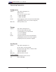
C2SEA/C2SEE User’s Manual Table of Contents Preface About This Manual ...................................................................................................... iii Manual Organization .................................................................................................... iii Conventions Used in the Manual .................................................................................. iii Chapter 1: Introduction 1-1 Overview .....................................................
Table of Contents 2-6 Connecting Cables .......................................................................................... 2-13 ATX/Auxiliary Power Connectors ........................................................... 2-13 GLAN1 Port .............................................................................................. 2-13 Universal Serial Bus (USB) ..................................................................... 2-14 GLAN1 Port .......................................................
C2SEA/C2SEE User’s Manual Chapter 3: Troubleshooting 3-1 Troubleshooting Procedures .............................................................................. 3-1 Before Power On....................................................................................... 3-1 No Power................................................................................................... 3-1 No Video ..................................................................................................
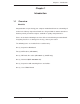
Chapter 1: Introduction Chapter 1 Introduction 1-1 Overview Checklist Congratulations on purchasing your computer motherboard from an acknowledged leader in the industry. Supermicro boards are designed with the utmost attention to detail to provide you with the highest standards in quality and performance. Please check that the following items have all been included with your motherboard. If anything listed here is damaged or missing, contact your retailer.
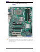
C2SEA/C2SEE User’s Manual C2SEA Motherboard Image Note: All pictures and drawings shown in this manual were based upon the latest PCB Revision available at the time of publishing of the manual. The motherboard you have received may or may not look exactly the same as those in this manual.
Chapter 1: Introduction Notes 1-3
C2SEA/C2SEE User’s Manual SMBUS_PS1 CPU Fan JPW2 KB/MOUSE Motherboard Layout VGA Fan1 J17 JPW1 DIMM2B DIMM2A DIMM4 DIMM3 DIMM1 J6 DIMM1B DIMM1A Intel G45 (C2SEA) G43 (C2SEE) HD AUDIO J4 Fan5 DIMM2 LAN1 J7 JPUSB1 J18 USB/0/1 USB2/3/4/5 J3 SPDIF_Out HDMI CPU Slot7 PCI-E x1 Slot6 PCI-E Gen2 x16 Lan CTRL LE1 Fan3 Fan2 C2SEA/C2SEE JPL1 SPI BIOS JBT1 CMOS CLEAR Slot5 PCI 33MHZ Intel JLED1 J12 FP Audio JF1 ICH10 Battery Slot4 PCI-E x4 on x16 JI2C2 JI2C1 JWD1 CD1 S I/
Chapter 1: Introduction C2SEA/C2SEE Quick Reference Jumpers Description Default Setting JBT1 CMOS Clear See Chapter 2 JD1 Onboard Speaker Enable Pins 3-4 (Enabled) JI2C1/JI2C2 SMB to PCI Slots See Chapter 2 JP11 (C2SEA) 1394_1/ 1394_2 Enable Pins 1-2 (Enabled) JPAC Audio Enable Pins 1-2 (Enabled) JPD1 (C2SEA) IDE Enable Pins 1-2 (Enabled) JPL1 Gigabit LAN 1/LAN 2 Enable Pins 1-2 (Enabled) JPUSB1/JPUSB2 USB 0-5 Enable/USB 6-11 Enable JWD Watch Dog Timer Out Pins 1-2 (Enabled) Pin
C2SEA/C2SEE User’s Manual Motherboard Features Processor • Single Intel Core 2™ Extreme/Quad/Duo processor with an FSB of 1333/1066/800 MHz Memory • Up to 8GB of Unbuffered non-ECC DDR3@1066/800 memory for single-channel or dual-channel interleaved mode in four DIMM sockets (C2SEA) • Up to 4GB of Unbuffered non-ECC DDR3@1066/800 memory for single-channel or dual-channel interleaved mode in two DIMM sockets (C2SEE) Chipset • • Intel G45 GMCH (C2SEA) or G43 GMCH (C2SEE) ICH10 Expansion Slots • •
Chapter 1: Introduction ACPI Features • • • • Slow blinking LED for suspend state indicator BIOS support for USB keyboard Main switch override mechanism External modem ring-on Onboard I/O • • • • • • • Built in ICH10 SATA Controller, 6 connectors for up to 6 devices One fast UART 16550 compatible serial port Realtek RTL8111C Gigabit Ethernet controllers PS/2 mouse and PS/2 keyboard ports ITE 8213F Controller supports one IDE channel & two devices (C2SEA only) 12 USB (Universal Serial Bus) 2.
C2SEA/C2SEE User’s Manual Block Diagram LGA775_Processor VRM 11.1 FSB: 1333/1066/800 PCIE_x16 DIMM_CHA DDR3:1066/800 DIMM_CHB G45(C2SEA) G43(C2SEE) MCH PCI_E x16 MUX & HDMI(C2SEA) Level Shift CRT DMI SATA x6 PCIE_X1 PCIE_x4 PCI_E x4 SATAII /300 USB x 12 Realtek RTL8111C ICH10 PCIE_x1 PCI_32_BUS USB2.0 PCI_E x1 Slot ITE 8213F IDE PCI 32 x4 (C2SEE) PCI 32 x2 (C2SEA) W83627DHG LPC I/O FAN x5 TI TSB43AB22A SPI HDA KB. MS.
Chapter 1: Introduction 1-2 Chipset Overview The Intel G45/G43 Express Chipset is specially designed for use with Intel Core 2™ Extreme/Core Quad/Core Duo LGA 775 processors. It consists of two primary components: the Graphics and Memory Controller Hub (GMCH), and the I/O Controller Hub (ICH10). The GMCH manages the data flow between the CPU interface, the System Memory interface, the External Graphics interface (or PCI-Express Interface), and the I/O Controller through the Direct Media Interface (DMI).
C2SEA/C2SEE User’s Manual 1-3 Recovery from AC Power Loss BIOS provides a setting for you to determine how the system will respond when AC power is lost and then restored to the system. You can choose for the system to remain powered off (in which case you must hit the power switch to turn it back on) or for it to automatically return to a power on state. See the Power Lost Control setting in the BIOS chapter of this manual to change this setting. The default setting is Power-Off.
Chapter 1: Introduction Slow Blinking LED for Suspend-State Indicator When the CPU goes into a suspend state, the chassis power LED will start blinking to indicate that the CPU is in suspend mode. When the user presses any key, the CPU will wake-up and the LED will automatically stop blinking and remain on. BIOS Support for USB Keyboard If the USB keyboard is the only keyboard in the system, it will function like a normal keyboard during system boot-up.
C2SEA/C2SEE User’s Manual 1-7 Versatile Media Capabilities High-Definition Audio and HDMI Connections The High-Definition Audio Controller, embedded in the ICH10, delivers up to four codecs, supporting different types of codecs. Operating at 3.3V or 1.5V, the embedded Audio Controller supports a multi-channel audio stream, 32-bit sample depth, up to 192 kHz of same rate, and can be used with a variety of microphones for input.
Chapter 2: Installation Chapter 2 Installation 2-1 Static-Sensitive Devices Electrostatic Discharge (ESD) can damage electronic components. To prevent damage to your system board, it is important to handle it very carefully. The following measures are generally sufficient to protect your equipment from ESD. Precautions • • Use a grounded wrist strap designed to prevent static discharge. Touch a grounded metal object before removing the board from the antistatic bag.
C2SEA/C2SEE User's Manual 2-3 Processor and Heatsink Installation Warning: When handling the processor package, avoid placing direct pressure on the label area of the fan. Notes: 1. Always connect the power cord last and always remove it before adding, removing or changing any hardware components. Make sure that you install the processor into the CPU LGA 775 socket before you install the CPU heatsink. 2. The Intel LGA 775 Processor package contains the CPU fan and heatsink assembly.
Chapter 2: Installation 3. Use your thumb and your index fin- Top Center Edge ger to hold the CPU at the top center edge and the bottom center edge of the CPU. 4. Align CPU Pin1 (the CPU corner marked with a triangle) against the socket corner that is marked with a Bottom Center Edge triangle cutout. golden dot 5. Align the CPU key that is the semi-circle cutout below a golden dot against the socket key, the Notch on the same side of the triangle cutout on the socket. 6.
C2SEA/C2SEE User's Manual Installing the Heatsink 1. Locate the CPU Fan on the motherboard. (Refer to the layout on the right for the CPU Fan location.) 2. Position the heatsink in such a way that the heatsink fan wires are closest to the CPU fan and are not interfered with other components. 3. Inspect the CPU Fan wires to make sure that the wires are routed through the bottom of the heatsink. 4. Remove the thin layer of the protective film from the copper core of the heatsink.
Chapter 2: Installation 8. Repeat Step 6 to insert all four heatsink fasteners into the mounting holes. 9. Once all four fasteners are securely inserted into the mounting holes and the heatsink is properly installed on the motherboard, connect the heatsink fan wires to the CPU Fan connector. Removing the Heatsink 1. Unplug the power cord from the power supply. 2. Disconnect the heatsink fan wires from the CPU fan header. 3.
C2SEA/C2SEE User's Manual 2-4 Installing DIMMs Note: Check the Supermicro web site for recommended memory modules. Warning: Exercise extreme care when installing or removing DIMM modules to prevent any possible damage. Also note that the memory is interleaved to improve performance (see step 1). DIMM Installation 1. Insert the desired number of DIMMs into the memory slots, starting with DIMM1A, DIMM2A, then, DIMM1B and DIMM2B 2. Insert each DIMM module vertically into its slot.
Chapter 2: Installation Possible System Memory Allocation & Availability System Device Size Physical Memory Remaining (-Available) (4 GB Total System Memory) Firmware Hub flash memory (System BIOS) 1 MB 3.99 Local APIC 4 KB 3.99 Area Reserved for the chipset 2 MB 3.99 I/O APIC (4 Kbytes) 4 KB 3.99 PCI Enumeration Area 1 256 MB 3.76 PCI Express (256 MB) 256 MB 3.51 PCI Enumeration Area 2 (if needed) -Aligned on 256-MB boundary- 512 MB 3.01 VGA Memory 16 MB 2.85 TSEG 1 MB 2.
C2SEA/C2SEE User's Manual 2-5 Control Panel Connectors/IO Ports The I/O ports are color coded in conformance with the PC 99 specification. See The figure below for the colors and locations of the various I/O ports. 1. Back Panel Connectors/IO Ports 9 18 8 12 15 7 11 14 17 6 10 13 16 2 C2SEA/C2SEE 1 3 4 5 Back Panel I/O Port Locations and Definitions Back Panel Connectors 1. Keyboard (Purple) 2. PS/2 Mouse (Green) 3. VGA 4. HDMI (C2SEA only) 5. S/PDIF_Out 6. USB Port 2 7.
Chapter 2: Installation 2. Front Control Panel JF1 contains header pins for various buttons and indicators that are normally located on a control panel at the front of the chassis. These connectors are designed specifically for use with Supermicro server chassis. See Figure 2-4 for the descriptions of the various control panel buttons and LED indicators. Refer to the following section for descriptions and pin definitions.
C2SEA/C2SEE User's Manual 3. Front Control Panel Pin Definitions Power LED Power LED Pin Definitions (JF1) The Power LED connection is located on pins 15 and 16 of JF1. Refer to the table on the right for pin definitions. Pin# Definition 15 LED_Anode+ 16 PWR LED Signal HDD LED The HDD LED connection is located on pins 13 and 14 of JF1. Attach a hard drive LED cable here to display disk activity (for any hard drives on the system, including SAS and Serial ATA).
Chapter 2: Installation NIC1 LED Indicators The NIC (Network Interface Controller) LED connection for GLAN port1 GLAN1 LED Pin Definitions (JF1) Pin# is located on pins 11 and 12 of JF1. Attach NIC LED cables to display network activity. Refer to the table on the right for pin definitions.
C2SEA/C2SEE User's Manual Reset Button Reset Button Pin Definitions (JF1) The Reset Button connection is located on pins 3 and 4 of JF1. Attach it to a hardware reset switch on the computer case. Refer to the table on the right for Pin# Definition 3 Reset 4 Ground pin definitions. Power Button The Power Button connection is located on pins 1 and 2 of JF1. Momentarily contacting both pins will power on/off the system.
Chapter 2: Installation 2-6 Connecting Cables ATX/Auxiliary Power Connectors ATX Power 24-pin Connector Pin Definitions A 24-pin main power connector is located at JPW1, and a 8-pin power Pin# Definition 13 +3.3V 1 +3.3V 14 -12V 2 +3.3V 15 COM 3 COM 16 PS_ON 4 +5V Note: The 8-pin 12V PWR sup- 17 COM 5 COM ply is also required to provide 18 COM 6 +5V 19 COM 7 COM 20 Res (NC) 8 PWR_OK 21 +5V 9 5VSB 22 +5V 10 +12V 23 +5V 11 +12V 24 COM 12 +3.
C2SEA/C2SEE User's Manual Universal Serial Bus (USB) Back Panel USB (0~5) There are 12 USB 2.0 (Universal Serial Bus) ports/headers on the motherboard. Six of them are Back Panel USB ports: USB 0~1 (J4) and USB 2~5 (J7). USB 6, USB 8~9 and USB10~11 Front Panel USB headers that can be accessed from the front Pin# Definitions 1 +5V 2 PO- 3 PO+ 4 Ground 5 N/A side of the chassis. See the tables on Front Accessible Panel USB (6, 8~9, 10~11) Connectors the right for pin definitions.
Chapter 2: Installation Overheat LED/Fan Fail (JOH1) Overheat LED Pin Definitions The JOH1 header is used to connect an LED to provide warning of chassis overheating. This LED will blink to indicate a fan failure. Refer to the table Pin# Definition 1 5vDC 2 OH Active on right for pin definitions. OH/Fan Fail LED Status State Message Solid Overheat Blinking Fan Fail Chassis Intrusion Chassis Intrusion Pin Definitions (JL1) A Chassis Intrusion header is located at JL1 on the motherboard.
C2SEA/C2SEE User's Manual Fan Headers The C2SEA/C2SEE has five chassis fan headers (Fan 1 to Fan 5). Fan 1 is the CPU Fan. Fan 2 to Fan 5 are system/ Fan Header Pin Definitions (Fan1-3) chassis fans. Note: Pins 1-3 of a 4-pin fan headers are backward compatible with the tradi- Pin# Definition 1 Ground tional 3-pin fans. See the table on the right 2 +12V for pin definitions.
Chapter 2: Installation ATX PS/2 Keyboard and PS/2 PS/2 Keyboard and Mouse Port Pin Definitions Mouse Ports The ATX PS/2 keyboard and the PS/2 Pin# Definition mouse are located on the backplane. 1 Data See the table on the right for pin defini- 2 NC 3 Ground 4 VCC 5 Clock 6 NC tions. (The mouse port is above the keyboard port. See the table on the right for pin definitions.
C2SEA/C2SEE User's Manual Wake-On-Ring Wake-On-Ring Pin Definitions (JWOR) The Wake-On-Ring header is designated JWOR. This function allows your computer to wake-up when Pin# Definition receiving an incoming call while in 1 Ground the suspend state. See the table on the right for pin definitions. You must 2 Wake-up have a Wake-On-Ring card and cable to use this feature. Wake-On-LAN Wake-On-LAN Pin Definitions (JWOL) The Wake-On-LAN header is located at JWOL on the motherboard.
Chapter 2: Installation SMB_PS1 Connector PWR SMB Pin Definitions 2 SMB_PS1 (I C) Connector monitors power supply, fan and system temperatures. See the table on the right for pin definitions. Pin# Definition 1 Clock 2 Data 3 PWR Fail 4 Ground 5 +3.3V High-Definition Audio (HDA) The C2SEA/C2SEE features a 7.1+2 Channel High-Defi nition Audio (HDA) (J8) codec that Orange: CEN/LFE Blue: Line-In provides 10 DAC channels, simultaneously supporting 7.
C2SEA/C2SEE User's Manual Front Panel Audio Control FP Audio Pin Definitions When front panel headphones are plugged in, the back panel audio output is disabled. This is Pin# Defin. 1 MIC_L done through the FP Audio header (J12). If the 2 AUD_GND front panel interface card is not connected to 3 MIC_R the front panel audio header, jumpers should be installed on the header (J12) pin pairs: 1-2, 5-6, 4 FP-Audio-Detect 5 Line_2_R 6 Ground and 9-10.
Chapter 2: Installation S/PDIF_Out Connector An S/PDIF_Out connector is located next to the Backpanel USB ports on the motherboard. The S/PDIF(Sony/Philips Digital Interface Format) connector is used for transporting stereo digital audio signals. It is commonly used to connect the output of a DVD player to a home theater receiver that supports Dolby Digital or DTS surround sound. The S/PDIF_Out connector includes the top component (S/PDIF_RCA) and the bottom component (S/PDIF).
C2SEA/C2SEE User's Manual 1394_1/1394_2 Connections (C2SEA only) 1394_1 Pin Definitions Pin# Defin. Pin# Defin 1394_1 and 1394_2 provide the IEEE 1 PTPA0+ 2 PTPA0- 1394a connections on the motherboard. 3 GND 4 GND See the tables on the right for pin definitions. 5 PTPB0+ 6 PTPB0- 7 PWR 1394 8 PWR 1394 9 NC 10 ZX J1394_2 Pin Definitions Pin# Defin.
Chapter 2: Installation 2-7 Jumper Settings Explanation of Jumpers Connector Pins 3 2 1 3 2 1 To modify the operation of the motherboard, jumpers can be used to choose between Jumper Cap optional settings. Jumpers create shorts between two pins to change the function of the connector. Pin 1 is identified with a square solder pad on the printed circuit Setting Pin 1-2 short board. See the motherboard layout pages for jumper locations.
C2SEA/C2SEE User's Manual Watch Dog Enable/Disable Watch Dog Jumper Settings (JWD) Watch Dog is a system monitor that can reboot the system when a software application Jumper Setting hangs. Close pins 1-2 to reset the system if an application hangs. Close pins 2-3 to generate a non-maskable interrupt signal for the application that hangs. See the table on the right Definition Pins 1-2 Reset (default) Pins 2-3 NMI Open Disabled for jumper settings. Watch Dog must also be enabled in the BIOS.
Chapter 2: Installation PCI/PCI-E Slots to SMB Speeds 2 SMBus to PCI-X/PCI-Exp Slots Jumper Settings 2 Jumpers JI C1/JI C2 allow you to connect Jumper Setting PCI/PCI-Exp. Slots to the System Management Bus. The default setting is open to disable the connection. See the table on the Definition Closed Enabled Open Disabled (Default) right for jumper settings. Clear CMOS JBT1 is used to clear CMOS. Instead of pins, this "jumper" consists of contact pads to prevent the accidental clearing of CMOS.
C2SEA/C2SEE User's Manual IDE Enable/Disable (C2SEA Only) IDE Enable (JPD1) JPD1 enables or disables IDE on the C2SEA. See the table on the right for Pin# Definition jumper settings. The default setting 1-2 Enabled (default) is Enabled. 2-3 Disabled Audio Enable Audio Enable (JPAC) JPAC enables or disables the onboard audio connections. See the table on the right for jumper settings. The default setting is Enabled. 1-2 Enabled (default) 2-3 Disabled SMBUS_PS1 CPU Fan JPW2 KB/MOUSE B.
Chapter 2: Installation USB Wake-Up Use JPUSB jumpers to enable the function of "System Wake-Up via USB devices", which allows you to "wake-up" the system by pressing a JPUSB1 (Back Panel USB Wake-up) key on the USB keyboard or by clicking the USB Pin# Definition mouse of your system. The JPUSB jumpers are used together with the USB Wake-Up function in 1-2 Enabled (Default) 2-3 Disabled the BIOS. Enable both the jumpers and the BIOS setting to allow the system to "wake-up via USB Devices".
C2SEA/C2SEE User's Manual Onboard Speaker Enable Onboard Speaker Enable Jumper Settings An onboard speaker (Buzzer) enable jumper is located at JD1 on the moth- Pin Setting Definition erboard. Close pins 3-4 to use the Pins 3-4 Onboard Speaker onboard speaker. Connect a cable to Pins 1-4 External Speaker A. Onboard Speaker EnSMBUS_PS1 CPU Fan JPW2 KB/MOUSE pins 1-4 to use an external speaker.
Chapter 2: Installation 2-8 Onboard Indicators GLAN LED Indicators There is a Gigabit-LAN port (LAN1) on the motherboard. This Gigabit Ethernet LAN Activity Link LED LED Rear View (When viewing from the rear side of the chassis.) port has two LED indicators. The green LED indicates activity; while the Link LED GLAN Link Indicator LED Settings may be green, amber or off to indicate the speed of the connection. See the tables LED Color at right for more information.
C2SEA/C2SEE User's Manual Onboard Power LED (LE1) The Onboard 3.3V Standby Power LED is located at LE1 on the motherboard. When Onboard PWR LED Indicator (LE1) LE1 is off, the system is off. When the LED Color Definition LED is on, the power is on. Unplug the Off System Off On Standby Power On power cable before removing or installing components. See the layout below for the LED location. SMBUS_PS1 CPU Fan JPW2 KB/MOUSE A.
Chapter 2: Installation 2-9 Parallel Port Connector and IDE Hard Drive Connections Note the following when connecting the hard disk drive cables: • A red mark on a wire typically designates the location of pin 1. Parallel Port Connector Parallel (Printer) Connector Pin Definitions The parallel (printer) connector is located at J13 on the motherboard. See the table on the right for pin definitions.
C2SEA/C2SEE User's Manual IDE Connector (C2SEAOnly) IDE Connector Pin Definitions There is one IDE Connector on the C2SEA. This connection supports two IDE devices. Be sure to close Pin 1 and Pin 2 of JPD1 to enable the IDE connector before using it. See the table on the right for pin definitions.
Chapter 3: Troubleshooting Chapter 3 Troubleshooting 3-1 Troubleshooting Procedures Use the following procedures to troubleshoot your system. If you have followed all of the procedures below and still need assistance, refer to the ‘Technical Support Procedures’ and/or ‘Returning Merchandise for Service’ section(s) in this chapter. Always disconnect the AC power cord before adding, changing or installing any hardware components. Before Power On 1.
C2SEA/C2SEE User's Manual 4. Turn the power switch on and off to test the system. 5. The battery on your motherboard may be old. Check to verify that it still supplies ~3VDC. If it does not, replace it with a new one. No Video 1. If the power is on but you have no video, remove all the add-on cards and cables. 2. Use the speaker to determine if any beep codes exist. Refer to Appendix A for details on beep codes. Note: If you are a system integrator, VAR or OEM, a POST diagnostics card is recommended.
Chapter 3: Troubleshooting 3-2 Technical Support Procedures Before contacting Technical Support, please take the following steps. Also, note that as a motherboard manufacturer, Supermicro does not sell directly to end-users, so it is best to first check with your distributor or reseller for troubleshooting services. They should know of any possible problem(s) with the specific system configuration that was sold to you. 1.
C2SEA/C2SEE User's Manual Question: How do I update my BIOS? Answer: It is recommended that you not upgrade your BIOS if you are not experiencing problems with your system. Updated BIOS files are located on our web site at (http://www.supermicro com/support/bios/). Please check our BIOS warning message and the information on how to update your BIOS on our web site. Also, check the current BIOS revision and make sure it is newer than your current BIOS before downloading.
Chapter 3: Troubleshooting drive(s). Consult the documentation that came with your disk drive for details on actual jumper locations and settings. 3-4 Returning Merchandise for Service A receipt or copy of your invoice marked with the date of purchase is required before any warranty service will be rendered. You can obtain service by calling your vendor for a Returned Merchandise Authorization (RMA) number.
C2SEA/C2SEE User's Manual Notes 3-6
Chapter 4: AMI BIOS Chapter 4 BIOS 4-1 Introduction This chapter describes the AMI BIOS Setup Utility for the C2SEA/C2SEE. The AMI ROM BIOS is stored in a Flash EEPROM and can be easily updated. This chapter describes the basic navigation of the AMI BIOS Setup Utility setup screens. Starting BIOS Setup Utility To enter the AMI BIOS Setup Utility screens, press the key while the system is booting up. Note: In most cases, the key is used to invoke the AMI BIOS setup screen.
C2SEA/C2SEE User’s Manual screens. An AMI BIOS identification string is displayed at the left bottom corner of the screen, below the copyright message. Warning!! Do not shut down or reset the system while updating BIOS to prevent possible boot failure. 4-2 Main Setup When you first enter the AMI BIOS Setup Utility, you will enter the Main setup screen. You can always return to the Main setup screen by selecting the Main tab on the top of the screen. The Main BIOS Setup screen is shown below.
Chapter 4: AMI BIOS Processor When you select this option, the AMI BIOS will automatically display the status of processors as shown below: Speed Count Core System Memory This option allows the AMI BIOS to display the status of memory modules installed in the system.
C2SEA/C2SEE User’s Manual 4-3 Advanced Setup Configurations Use the arrow keys to select Boot Setup and hit to access the submenu items: XBIOS Features QuickBoot If Enabled, this option will skip certain tests during POST to reduce the time needed for system boot. The options are Enabled and Disabled. QuietBoot This option allows the bootup screen options to be modified between POST messages or the OEM logo. Select Disabled to allow the computer system to display the POST messages.
Chapter 4: AMI BIOS XACPI Configuration Use this feature to configure ACPI (Advanced Configuration and Power Interface) power management settings for your system. ACPI Aware OS Select Yes to enable ACPI support for the OS. Disable this feature if ACPI is not supported by your OS. The options are Yes and No. Suspend Mode This setting allows you to configure the ACPI (Advanced Configuration and Power Interface) state for your system when it is in the Supsend mode. The options are S1, S3 and Auto.
C2SEA/C2SEE User’s Manual 19 at boot and allow the drives that are attached to these host adaptors to function as bootable disks. If this item is set to Disabled, the ROM BIOS of the host adaptors will not capture Interrupt 19, and the drives attached to these adaptors will not function as bootable devices. XProcessor & Clock Options Warning ! When you first enter the Advanced Setup screen, the Setup Warning will be displayed.
Chapter 4: AMI BIOS off and restart the system for the change to take effect. Please refer to Intel’s web site for detailed information. Execute Disable Bit (Available when supported by the OS and the CPU) Set to Enabled to enable the Execute Disable Bit to allow the processor to classify areas in the system memory where an application code can execute and where it cannot, thus preventing a worm or a virus from creating a flood of codes to overwhelm the processor or damage the system during an attack.
C2SEA/C2SEE User’s Manual XAdvanced Chipset Settings The items included in the Advanced Settings submenu are listed below: XNorthBridge Configuration This feature allows the user to configure the settings for the Intel 945GME NorthBridge chipset. Memory Remap Feature PCI memory resources will overlap with the total physical memory if 4GB of memory or above is installed on the motherboard.
Chapter 4: AMI BIOS IGD GTT Graphics Memory Size This feature allows the user to select the IGD GTT Graphics Size. The Default setting is No VT Mode, 2 MB. PAVP Mode Use the feature to select the Protect Audio Video Path Mode. The options are Disabled, Lite, and Paranoid. PEG Port Configuration PEG Port Use the feature to configure the PEG Port. The Default setting is Auto to allow the PEG Port to be automatically detected and configured by the BIOS.
C2SEA/C2SEE User’s Manual TV Standard This feature allows the user to determine how TV-Standard is handled by the system. The options are VBIOS-Default, NTSC, PAL, SECAM, SMPTE 240M, ITU-R-Television, SMPTE 295M, SMPTE 296M, EIA-770.2, and EIA-770.3. Spread Spectrum Mode If Enabled, the BIOS will monitor the level of Electromagnetic Interference caused by the components and will attempt to decrease the interference whenever needed. The options are Enabled and Disabled.
Chapter 4: AMI BIOS XUSB Configuration This feature allows the user to configure USB settings for the motherboard. USB Devices Enabled This item displays the USB devices that are detected by the BIOS. Legacy USB Support Select Enabled to use Legacy USB devices. If this item is set to Auto, Legacy USB support will be automatically enabled if a legacy USB device is installed on the motherboard, and vise versa. The settings are Disabled, Enabled and Auto. USB 2.
C2SEA/C2SEE User’s Manual Configure SATA#1 As This feature allows the user to select the drive type for SATA#1. The options are IDE and AHCI. Primary IDE Channels Master/Slave, Secondary IDE Channels Maser/Slave and Third IDE Channels Maser/Slave These settings allow the user to set the parameters of Primary IDE Master/Slave, Secondary IDE Master/Slave and Third IDE Master/Slave slots. Hit to activate the following submenu screen for detailed options of these items.
Chapter 4: AMI BIOS DMA Mode Select Auto to allow the BIOS to automatically detect IDE DMA mode when the IDE disk drive support cannot be determined. Select SWDMA0 to allow the BIOS to use Single Word DMA mode 0. It has a data transfer rate of 2.1 MBs. Select SWDMA1 to allow the BIOS to use Single Word DMA mode 1. It has a data transfer rate of 4.2 MBs. Select SWDMA2 to allow the BIOS to use Single Word DMA mode 2. It has a data transfer rate of 8.3 MBs.
C2SEA/C2SEE User’s Manual XPCI/PnP Configuration This feature allows the user to set the PCI/PnP configurations for the following items: Clear NVRAM Select Yes to clear NVRAM during system boot. The options are Yes and No. Plug & Play OS Select Yes to allow the OS to configure Plug & Play devices. (This is not required for system boot if your system has an OS that supports Plug & Play.) Select No to allow the AMI BIOS to configure all devices in the system.
Chapter 4: AMI BIOS XSuper IO Configuration Serial Port1 Address This option specifies the base I/O port address and the Interrupt Request address of Serial Port 1. Select Disabled to prevent the serial port from accessing any system resources. When this option is set to Disabled, the serial port physically becomes unavailable. Select 3F8/IRQ4 to allow the serial port to use 3F8 as its I/O port address and IRQ 4 for the interrupt address. The options are Disabled, 2F8/IRQ3, 3F8/IRQ4, 3E8/IRQ4, 2E8/IRQ3.
C2SEA/C2SEE User’s Manual XHardware Health Configuration This feature allows the user to monitor Hardware Health of the system and review the status of each item when displayed. System Temperature, CPU Temperature Fan Speed Control Modes This feature allows the user to decide how the system controls the speeds of the onboard fans. The CPU temperature and the fan speed are correlative. When the CPU on-die temperature increases, the fan speed will also increase, and vice versa.
Chapter 4: AMI BIOS 4-4 Security Settings The AMI BIOS provides a Supervisor and a User password. If you use both passwords, the Supervisor password must be set first. Supervisor Password Is: This item indicates if a supervisor password has been entered for the system. Clear means such a password has not been used and Set means a supervisor password has been entered for the system. User Password Is: This item indicates if a user password has been entered for the system.
C2SEA/C2SEE User’s Manual 4-5 Boot Configuration Use this feature to configure Boot Settings: XBoot Device Priority This feature allows the user to specify the sequence of priority for the Boot Device. The settings are 1st Floppy Drive and Disabled. The default settings are the following: • 1st boot device – 1st Floppy Drive XRemovable Drives This feature allows the user to specify the boot sequence from available Removable Drives.
Chapter 4: AMI BIOS 4-6 Exit Options Select the Exit tab from the AMI BIOS Setup Utility screen to enter the Exit BIOS Setup screen. Save Changes and Exit When you have completed the system configuration changes, select this option to leave the BIOS Setup Utility and reboot the computer, so the new system configuration parameters can take effect. Select Save Changes and Exit from the Exit menu and press .
C2SEA/C2SEE User’s Manual Load Fail-Safe Defaults To set this feature, select Load Fail-Safe Defaults from the Exit menu and press . The Fail-Safe settings are designed for maximum system stability, but not for maximum performance.
Appendix A: AMIBIOS Error Beep Codes Appendix A BIOS Error Beep Codes During the POST (Power-On Self-Test) routines, which are performed each time the system is powered on, errors may occur. Non-fatal errors are those which, in most cases, allow the system to continue the boot-up process. The error messages normally appear on the screen. Fatal errors are those which will not allow the system to continue the boot-up procedure.
C2SEA/C2SEE User’s Manual Notes A-2
Appendix B: BIOS POST Checkpoint Codes Appendix B BIOS POST Checkpoint Codes When the AMIBIOS performs the Power On Self Test, it writes checkpoint codes to I/O port 0080h. If the computer cannot complete the boot process, diagnostic equipment can be attached to the computer to read I/O port 0080h. B-1 Uncompressed Initialization Codes The uncompressed initialization checkpoint codes are listed in order of execution: Checkpoint Code Description D0h The NMI is disabled. Power on delay is starting.
C2SEA/C2SEE User's Manual B-2 Bootblock Recovery Codes The bootblock recovery checkpoint codes are listed in order of execution: Checkpoint Code Description E0h The onboard floppy controller if available is initialized. Next, beginning the base 512 KB memory test. E1h Initializing the interrupt vector table next. E2h Initializing the DMA and Interrupt controllers next. E6h Enabling the floppy drive controller and Timer IRQs. Enabling internal cache memory. Edh Initializing the floppy drive.
Appendix B: BIOS POST Checkpoint Codes B-3 Uncompressed Initialization Codes The following runtime checkpoint codes are listed in order of execution. These codes are uncompressed in F0000h shadow RAM. Checkpoint Code Description 03h The NMI is disabled. Next, checking for a soft reset or a power on condition. 05h The BIOS stack has been built. Next, disabling cache memory. 06h Uncompressing the POST code next. 07h Next, initializing the CPU and the CPU data area.
C2SEA/C2SEE User's Manual Checkpoint Code Description 25h Interrupt vector initialization is done. Clearing the password if the POST DIAG switch is on. 27h Any initialization before setting video mode will be done next. 28h Initialization before setting the video mode is complete. Configuring the monochrome mode and color mode settings next. 2Ah Bus initialization system, static, output devices will be done next, if present. See the last page for additional information.
Appendix B: BIOS POST Checkpoint Codes Checkpoint Code Description 4Ch The memory below 1 MB has been cleared via a soft reset. Clearing the memory above 1 MB next. 4Dh The memory above 1 MB has been cleared via a soft reset. Saving the memory size next. Going to checkpoint 52h next. 4Eh The memory test started, but not as the result of a soft reset. Displaying the first 64 KB memory size next. 4Fh The memory size display has started. The display is updated during the memory test.
C2SEA/C2SEE User's Manual Checkpoint Code Description 86h The password was checked. Performing any required programming before WINBIOS Setup next. 87h The programming before WINBIOS Setup has completed. Uncompressing the WINBIOS Setup code and executing the AMIBIOS Setup or WINBIOS Setup utility next. 88h Returned from WINBIOS Setup and cleared the screen. Performing any necessary programming after WINBIOS Setup next. 89h The programming after WINBIOS Setup has completed.
Appendix B: BIOS POST Checkpoint Codes Checkpoint Code Description A9h Returned from adaptor ROM at E000h control. Performing any initialization required after the E000 option ROM had control next. Aah Initialization after E000 option ROM control has completed. Displaying the system configuration next. Abh Uncompressing the DMI data and executing DMI POST initialization next. B0h The system configuration is displayed. B1h Copying any code to specific areas.
C2SEA/C2SEE User's Manual Notes B-8
Appendix C: Software Installation Instructions Appendix C Software Installation Instructions C-1 Installing Drivers After you've installed the Windows Operating System, a screen as shown below will appear. You are ready to install software programs and drivers that have not yet been installed. To install these software programs and drivers, click the icons to the right of these items.
C2SEA/C2SEE User's Manual C-2 Configuring Supero Doctor III The Supero Doctor III program is a Web-base management tool that supports remote management capability. It includes Remote and Local Management tools. The local management is called the SD III Client. The Supero Doctor III program included on the CDROM that came with your motherboard allows you to monitor the environment and operations of your system.
Appendix C: Software Installation Instructions Supero Doctor III Interface Display Screen-II (Remote Control) Note: SD III Software Revision 1.0 can be downloaded from our Web site at: ftp://ftp.supermicro.com/utility/Supero_Doctor_III/. You can also download SDIII User's Guide at: http://www.supermicro.com/PRODUCT/ Manuals/SDIII/UserGuide.pdf. For Linux, we will still recommend that you use Supero Doctor II.
C2SEA/C2SEE User's Manual Notes C-4