SUPER H8SCM H8SCM-F USER’S MANUAL Revision 1.
The information in this User’s Manual has been carefully reviewed and is believed to be accurate. The vendor assumes no responsibility for any inaccuracies that may be contained in this document, and makes no commitment to update or to keep current the information in this manual, or to notify any person or organization of the updates. Please Note: For the most up-to-date version of this manual, please see our web site at www.supermicro.com. Super Micro Computer, Inc.
Preface Preface About This Manual This manual is written for system integrators, PC technicians and knowledgeable PC users. It provides information for the installation and use of the H8SCM(-F) serverboard. The H8SCM(-F) serverboard is based on the AMD® SR5650/SP5100 chipset and supports one AMD Socket C32 type processor with up to 32 GB of ECC/Non-ECC UDIMM or up to 128 GB of ECC RDIMM SDRAM memory. The H8SCM serverboard does not have IPMI capability, whereas the H8SCM-F serverboard does.
Table of Contents Table of Contents Chapter 1 Introduction 1-1 Overview ......................................................................................................... 1-1 Checklist .......................................................................................................... 1-1 1-2 Contacting Supermicro .................................................................................... 1-2 1-3 Serverboard Features ...............................................................
H8SCM(-F) SERVERBOARD USER'S MANUAL NMI Button ............................................................................................... 2-13 LAN1/2 (Ethernet Ports) ........................................................................... 2-13 Universal Serial Bus Ports ....................................................................... 2-13 Chassis Intrusion ..................................................................................... 2-14 USB Headers .................................
Table of Contents Building a Driver Diskette ......................................................................... 2-24 Enabling SATA RAID in the BIOS ................................................................. 2-25 Using the DotHill and Adaptec RAID Utility .................................................. 2-27 Installing the RAID Driver During OS Installation ......................................... 2-27 2-13 Installing Drivers.................................................................
Chapter 1: Introduction Chapter 1 Introduction 1-1 Overview Checklist Congratulations on purchasing your computer motherboard from an acknowledged leader in the industry. Supermicro boards are designed with the utmost attention to detail to provide you with the highest standards in quality and performance. Please check that the following items have all been included with your motherboard. If anything listed here is damaged or missing, contact your retailer.
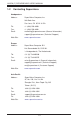
H8SCM(-F) SERVERBOARD USER'S MANUAL 1-2 Contacting Supermicro Headquarters Address: Super Micro Computer, Inc. 980 Rock Ave. San Jose, CA 95131 U.S.A. Tel: +1 (408) 503-8000 Fax: +1 (408) 503-8008 Email: marketing@supermicro.com (General Information) Web Site: www.supermicro.com support@supermicro.com (Technical Support) Europe Address: Super Micro Computer B.V.
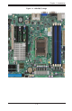
Chapter 1: Introduction Figure 1-1.
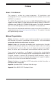
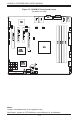
H8SCM(-F) SERVERBOARD USER'S MANUAL Figure 1-2. H8SCM(-F) Serverboard Layout (not drawn to scale) LAN1 LAN2 KB/Mouse COM1 USB0/1 IPMI_LAN VGA DP1 BMC JPL2 JPL1 JPW1 JOH1 DIMM1A JPI2C1 CPU DIMM1B DIMM2A DIMM2B USB4/5 SLOT7 PCI-E 2.0 X8 / X16 (IN X16) JI2C1 JI2C2 SLOT6 PCI-E 2.0 X8 JLPC1 SLOT4 PCI 33MHz SLOT5 PCI-E 2.
Chapter 1: Introduction H8SCM(-F) Quick Reference Jumper Description Default Setting JBT1 CMOS Clear (See Section 2-8) JCF1 Compact Flash Master/Slave Closed (Master) JI2C1/JI2C2 I2C to PCI-E Slot Enable/Disable Both Open (Disabled) JPB1 BMC Enable/Disable Pins 1-2 (Enabled) JPG1 VGA Enable/Disable Pins 1-2 (Enabled) JPL1 LAN 1 Enable/Disable Pins 1-2 (Enabled) JPL2 LAN 2 Enable/Disable Pins 1-2 (Enabled) JWD1 Watch Dog Pins 1-2 (Reset) LED Description LAN Ports LEDs for the L
H8SCM(-F) SERVERBOARD USER'S MANUAL Connector Description COM1/COM2 COM1 Serial Port/Header FAN 1-5 Chassis/CPU Fan Headers IDE#1 IDE Disk Drive Connector IPMI LAN (H8SCM-F only) Dedicated IPMI LAN Port (H8SCM-F only) JD1 Speaker Header JF1 Front Panel Connector JL1 Chassis Intrusion Header JOH1 Overheat Warning Header JIPMB (H8SCM-F only) System Management Bus Header for the IPMI Slot JPI2C1 Power I2C Header JPW1 24-pin Main ATX Power Connector JPW2 +12V 8-pin CPU Power Connectors
Chapter 1: Introduction 1-3 Serverboard Features CPU • Single AMD Opteron 4000 series (AMD Socket C32 type) processor Note: Refer to our web site for details on supported processors. Memory • Up to four (4) single and dual channel DIMM slots that support up to 32 GB of ECC/ Non-ECC UDIMM or up to 128 GB of ECC RDIMM DDR3-1600/1333/1066 Mhz speed, 1 GB, 2 GB, 4 GB, 8 GB, 16 GB or 32 GB size SDRAM memory in 1.5V or 1.35V voltages.
H8SCM(-F) SERVERBOARD USER'S MANUAL • Chipkill Support ACPI Features • Microsoft OnNow • Slow blinking LED for suspend state indicator • BIOS support for USB keyboard • Wake-On-LAN (WOL) Onboard I/O • Six (6) SATA ports supported by an on-chip SATA controller (RAID 0, 1 and 10 supported) • Seven (7) USB (Universal Serial Bus 2.
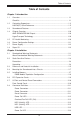
Chapter 1: Introduction Figure 1-3. AMD SR5650/SP5100 Chipset: System Block Diagram DIMM 1A DIMM 1B CPU1 DIMM 2A DIMM 2B HT3 Link 16/16-2.
H8SCM(-F) SERVERBOARD USER'S MANUAL 1-4 Chipset Overview The H8SCM(-F) serverboard is based on the AMD SR5650/SP5100 chipset. This chipset functions as a Media and Communications Processor (MCP). Controllers for the system memory are integrated directly into AMD Opteron processors. AMD SR5650/SP5100 Chipset The AMDSR5650/SP5100 are each a single-chip, high-performance HyperTransport peripheral controller.
Chapter 1: Introduction CPU Overheat/Fan Fail LED and Control This feature is available when the user enables the CPU overheat/Fan Fail warning function in the BIOS. This allows the user to define an overheat temperature. When this temperature is exceeded or when a fan failure occurs, the Overheat/Fan Fail warning LED is triggered.
H8SCM(-F) SERVERBOARD USER'S MANUAL Main Switch Override Mechanism The power button can function as a system suspend button. When the user depresses the power button, the system will enter a SoftOff state. The monitor will be suspended and the hard drive will spin down. Depressing the power button again will cause the whole system to wake-up. During the SoftOff state, the power supply provides power to keep the required circuitry in the system alive.
Chapter 1: Introduction 1-8 Super I/O The disk drive adapter functions of the Super I/O Winbond® BMC chip includes a data separator, write pre-compensation circuitry, decode logic, data rate selection, a clock generator, drive interface control logic and interrupt and DMA logic. The wide range of functions integrated onto the Super I/O greatly reduces the number of components required for interfacing with floppy disk drives.
H8SCM(-F) SERVERBOARD USER'S MANUAL Notes 1-14
Chapter 2: Installation Chapter 2 Installation 2-1 Standardized Warning Statements About Standardized Warning Statements The following statements are industry standard warnings, provided to warn the user of situations which have the potential for bodily injury. Should you have questions or experience difficulty, contact Supermicro's Technical Support department for assistance. Only certified technicians should attempt to install or configure components.
H8SCM(-F) SERVERBOARD USER'S MANUAL Warnung Bei Einsetzen einer falschen Batterie besteht Explosionsgefahr. Ersetzen Sie die Batterie nur durch den gleichen oder vom Hersteller empfohlenen Batterietyp. Entsorgen Sie die benutzten Batterien nach den Anweisungen des Herstellers. Attention Danger d'explosion si la pile n'est pas remplacée correctement. Ne la remplacer que par une pile de type semblable ou équivalent, recommandée par le fabricant.
Chapter 2: Installation Product Disposal Warning! Ultimate disposal of this product should be handled according to all national laws and regulations. 製品の廃棄 この製品を廃棄処分する場合、国の関係する全ての法律・条例に従い処理する必要が あります。 警告 本产品的废弃处理应根据所有国家的法律和规章进行。 警告 本產品的廢棄處理應根據所有國家的法律和規章進行。 Warnung Die Entsorgung dieses Produkts sollte gemäß allen Bestimmungen und Gesetzen des Landes erfolgen. ¡Advertencia! Al deshacerse por completo de este producto debe seguir todas las leyes y reglamentos nacionales.
H8SCM(-F) SERVERBOARD USER'S MANUAL 2-2 Static-Sensitive Devices Electrostatic Discharge (ESD) can damage electronic components. To prevent damage to your system board, it is important to handle it very carefully. The following measures are generally sufficient to protect your equipment from ESD. Precautions • • • • • • • Use a grounded wrist strap designed to prevent static discharge. Touch a grounded metal object before removing the board from the antistatic bag.
Chapter 2: Installation 2-3 Processor and Heatsink Installation Caution: Exercise extreme caution when handling and installing the processor. Always connect the power cord last and always remove it before adding, removing or changing any hardware components. Installation Procedure Follow the procedures as listed below to install the motherboard into a chassis. 1. Install the processor(s) and the heatsink(s). 2. Install the motherboard in the chassis. 3. Install the memory and add-on cards. 4.
H8SCM(-F) SERVERBOARD USER'S MANUAL 3. Align pin 1 of the CPU with pin 1 of the socket. Once aligned, carefully place the CPU into the socket. Do not drop the CPU on the socket, move the CPU horizontally or vertically or rub the CPU against the socket or against any pins of the socket, which may damage the CPU and/or the socket. 4. With the CPU inserted into the socket, inspect the four corners of the CPU to make sure that it is properly installed and flush with the socket.
Chapter 2: Installation 2-4 Mounting the Serverboard into a Chassis All motherboards have standard mounting holes to fit different types of chassis. Make sure that the locations of all the mounting holes for both the motherboard and the chassis match. Although a chassis may have both plastic and metal mounting fasteners, metal ones are highly recommended because they ground the motherboard to the chassis. Make sure that the metal standoffs click in or are screwed in tightly.
H8SCM(-F) SERVERBOARD USER'S MANUAL Figure 2-1. Installing DIMM into Slot To Install: Insert module vertically and press down until it snaps into place. Pay attention to the alignment notch at the bottom. Notch Notch Front View To Remove: Use your thumbs to gently Release Tab push the release tabs near both ends of the module. This should release it from the slot. Note: Notch should align with the receptive key point on the slot.
Chapter 2: Installation DIMM Module Population Configuration For memory to work properly, follow the tables below for memory installation: Per Channel DIMM Populations Options DIMM Type Unbuffered DIMM (UDIMM) Registered DIMM (RDIMM) DIMM A DIMM B Max. MHz, 1.5V DIMMs Max. MHz, 1.35V DIMMs (6-core Only) Max.
H8SCM(-F) SERVERBOARD USER'S MANUAL 2-7 I/O Port and Control Panel Connections The I/O ports are color coded to make setting up your system easier. See Figure 2-2 below for the colors and locations of the various I/O ports. Figure 2-2. I/O Port Locations and Definitions 2 1 4 3 5 6 7 8 Rear I/O Ports 1. Keyboard 5. COM1 2. PS/2 Mouse 6. VGA Port 3. USB0/1 7. LAN1 4. IPMI LAN (H8SCM-F Only) 8. LAN2 Front Control Panel JF1 contains header pins for various front control panel connectors.
Chapter 2: Installation 2-8 Connector Definitions ATX Power 24-pin Connector Pin Definitions (JPW1) Power Connectors Pin# Definition Pin# Definition A 24-pin main power supply connector(JPW1) and three 8-pin CPU PWR connector (JPW2) on the motherboard. These power connectors meet the SSI EPS 12V specification. In addition to the 24-pin ATX power connector, the 12V 8-pin CPU PWR connector at JPW2 must also be connected to your power supply. See the table on the right for pin definitions. 13 +3.
H8SCM(-F) SERVERBOARD USER'S MANUAL Power Fail LED The Power Fail LED connection is located on pins 5 and 6 of JF1. Refer to the table on the right for pin definitions. PWR Fail LED Pin Definitions (JF1) Pin# Definition 5 3.3V 6 Power Fail LED Overheat/Fan Fail LED (OH) Connect an LED to the OH connection on pins 7 and 8 of JF1 to provide advanced warning of chassis overheating or fan failure. Refer to the table on the right for pin definitions and status indicators.
Chapter 2: Installation Power On LED Power LED Pin Definitions (JF1) The Power On LED connector is located on pins 15 and 16 of JF1. This connection is used to provide LED indication of power being supplied to the system. See the table on the right for pin definitions. Pin# Definition 15 Vcc 16 Power LED NMI Button NMI Button Pin Definitions (JF1) The non-maskable interrupt button header is located on pins 19 and 20 of JF1. Refer to the table on the right for pin definitions.
H8SCM(-F) SERVERBOARD USER'S MANUAL Chassis Intrusion Chassis Intrusion Pin Definitions (JL1) A Chassis Intrusion header is located at JL1. Attach the appropriate cable to inform you of a chassis intrusion. USB Headers Four USB 2.0 headers (USB2/3 and USB4/5) are also included on the motherboard. These may be connected to provide front side access. A USB cable (not included) is needed for the connection. See the table on the right for pin definitions.
Chapter 2: Installation SGPIO The T-SGPIO1/ T-SGPIO2 (Serial General Purpose Input/Output) headers provide a bus between the SATA controller and the backpane to provide SATA enclosure management functions. Connect the appropriate cable from the backplane to the T-SGPIO1 header to utilize SATA management functions on your system. Trusted Platform Module Header The JLPC1 header is used to connect a Trusted Platform Module (TPM), available separately from a third-party vendor.
H8SCM(-F) SERVERBOARD USER'S MANUAL ATX PS/2 Keyboard and PS/2 Mouse Ports PS/2 Keyboard/Mouse Pin Definitions The ATX PS/2 keyboard and PS/2 mouse are located next to the Back Panel USB Ports 0/1 on the motherboard. See the table at right for pin definitions.
Chapter 2: Installation Overheat LED Connect an LED to the JOH1 header to provide warning of chassis overheating. See the table on the right for pin definitions. Overheat LED Pin Definitions (JOH1) Pin# Definition 1 3.3V 2 OH Active Wake-On-LAN T h e Wa k e - O n - L A N h e a d e r i s designated JWOL1. See the table on the right for pin definitions. You must have a LAN card with a Wake-On-LAN connector and cable to use the WakeOn-LAN feature.
H8SCM(-F) SERVERBOARD USER'S MANUAL 2-9 Jumper Settings 3 2 1 3 2 1 Connector Pins Explanation of Jumpers To modify the operation of the motherboard, jumpers can be used to choose between optional settings. Jumpers create shorts between two pins to change the function of the connector. Pin 1 is identified with a square solder pad on the printed circuit board. See the diagram at right for an example of jumping pins 1 and 2. Refer to the motherboard layout page for jumper locations.
Chapter 2: Installation LAN1/2 Enable/Disable LAN1/2 En/Disable Jumper Settings (JPL1/JPL2) Change the setting of jumper JPL1 or JPL2 to enable or disable the LAN1 or LAN2 Ethernet port. See the table on the right for jumper settings. The default setting is enabled. VGA Enable/Disable Definition Pins 1-2 Enabled Pins 2-3 Disabled VGA Enable/Disable Jumper Settings (JPG1) JPG1 allows you to enable or disable the VGA port. The default position is on pins 1 and 2 to enable VGA.
H8SCM(-F) SERVERBOARD USER'S MANUAL Onboard Speaker Enable/Disable The JD1 header allows you to use either an external speaker or the internal (onboard) speaker. To use the internal onboard speaker, close pins 6 and 7 with a jumper. To use an external speaker, remove the jumper and connect the speaker wires to pins 4 (+5V) and 7 (control signal). See the table on the right for settings and the table associated with the Power LED/ Keylock/Speaker connection (previous section) for jumper settings.
Chapter 2: Installation GLAN LED 2-10 Onboard Indicators Activity LED Link Speed LED GLAN LEDs There are two LAN ports (LAN1/2) on the motherboard. Each Ethernet LAN port has two LEDs. The Yellow LED on the right indicates connection and activity. The Link LED on the left side may be green, amber or off to indicate the speed of the connection. See the tables at right for more information.
H8SCM(-F) SERVERBOARD USER'S MANUAL Power LED Power LED (DP2) DP2 is an Onboard Power LED. When this LED is lit, it means power is present on the serverboard. Be sure to turn off the system and unplug the power cord(s) before removing or installing components. State System Status On Standby power present on motherboard Off No power connected 2-11 IDE and SATA Drive Connections Use the following information to connect the IDE hard disk drive cables.
Chapter 2: Installation IDE Connector There is one IDE connector on the serverboard. See the table on the right for pin definitions.
H8SCM(-F) SERVERBOARD USER'S MANUAL 2-12 Enabling SATA RAID Now that the hardware is set up, you must install the operating system and the SATA RAID drivers, if you wish to use RAID with your SATA drives. The installation procedure differs depending on whether you wish to have the operating system installed on a RAID array or on a separate non-RAID drive. See the instructions below for details.
Chapter 2: Installation Enabling SATA RAID in the BIOS Before installing the Windows operating system, you must change some settings in the BIOS. Boot up the system and hit the key to enter the BIOS Setup Utlility. After the setup utility loads, 1. Use the arrow keys to move to the "Exit" menu. Scroll down using the arrow keys to "Load Optimal Defaults" and press . Select "OK" to confirm, then to load the default settings. 2.
H8SCM(-F) SERVERBOARD USER'S MANUAL Figure 2-5. DotHill RAID Utility Program Screen Figure 2-6.
Chapter 2: Installation Using the DotHill and Adaptec RAID Utility The RAID Utility program allows you to define the drives you want to include in the RAID array and the mode and type of RAID. Installing the RAID Driver During OS Installation You may also use the procedure below to install the RAID driver during the Windows OS installation: 1. With the Windows OS installation CD-ROM in the CD drive, restart the system. 2. Press again to continue with the Windows setup. 3.
H8SCM(-F) SERVERBOARD USER'S MANUAL 2-13 Installing Drivers The Supermicro Website contains drivers and utilities for your system at ftp://ftp. supermicro.com, some of which must be installed, such as the chipset driver. After downloading and installing the drivers and utilities, the display shown in Figure 2-7 should appear. Click the icons showing a hand writing on paper to view the readme files for each item.
Chapter 2: Installation Supero Doctor III The SuperDoctor® III program is a Web base management tool that supports remote management capability. It includes Remote and Local Management tools. The local management is called SD III Client. The SuperDoctor III program included on the CD-ROM that came with your motherboard allows you to monitor the environment and operations of your system. SuperDoctor III displays crucial system information such as CPU temperature, system voltages and fan status.
H8SCM(-F) SERVERBOARD USER'S MANUAL Figure 2-9. Supero Doctor III Interface Display Screen (Remote Control) Note: The SuperDoctor III program and User’s Manual can be downloaded from the Supermicro web site at http://www.supermicro.com/products/accessories/software/ SuperDoctorIII.cfm.For Linux, we recommend that you use the SuperoDoctor II application instead.
Chapter 2: Installation 2-14 Serverboard Battery Caution: There is a danger of explosion if the onboard battery is installed upside down, which will reverse its polarites (see Figure 2-10). This battery must be replaced only with the same or an equivalent type recommended by the manufacturer (CR2032). Dispose of used batteries according to the manufacturer's instructions. Figure 2-10. Installing the Onboard Battery Please handle used batteries carefully.
H8SCM(-F) SERVERBOARD USER'S MANUAL Notes 2-32
Chapter 3: Troubleshooting Chapter 3 Troubleshooting 3-1 Troubleshooting Procedures Use the following procedures to troubleshoot your system. If you have followed all of the procedures below and still need assistance, refer to the ‘Technical Support Procedures’ and/or ‘Returning Merchandise for Service’ section(s) in this chapter. Always disconnect the AC power cord before adding, changing or installing any hardware components. Before Power On 1.
H8SCM(-F) Serverboard User's Manual No Video 1. If the power is on but you have no video, remove all the add-on cards and cables. 2. Use the speaker to determine if any beep codes exist. Refer to Appendix A for details on beep codes. Note: If you are a system integrator, VAR or OEM, a POST diagnostics card is recommended. For I/O port 80h codes, refer to App. B. Memory Errors 1. Make sure that the DIMM modules are properly and fully installed. 2.
Chapter 3: Troubleshooting 2. BIOS upgrades can be downloaded from our web site. Note: Not all BIOS can be flashed depending on the modifications to the boot block code. 3.
H8SCM(-F) Serverboard User's Manual Question: Why can't I turn off the power using the momentary power on/off switch? Answer: The instant power off function is controlled in BIOS by the Power Button Mode setting. When the On/Off feature is enabled, the motherboard will have instant off capabilities as long as the BIOS has control of the system.
Chapter 4: BIOS Chapter 4 BIOS 4-1 Introduction This chapter describes the AMIBIOS™ Setup utility for the H8SCM(-F) serverboard. The 16 Mb AMI BIOS® is stored in a flash chip and can be easily upgraded using a floppy disk-based program. Note: Due to periodic changes to the BIOS, some settings may have been added or deleted and might not yet be recorded in this manual. Please refer to the Manual Download area of our web site for any changes to BIOS that may not be reflected in this manual.
H8SCM(-F) SERVERBOARD USER'S MANUAL 4-2 Main Menu When you first enter AMI BIOS Setup Utility, you will see the Main Menu screen. You can always return to the Main Menu by selecting the Main tab on the top of the screen with the arrow keys. The Main Menu screen provides you with a system overview, which includes the version, built date and ID of the AMIBIOS, the type, speed and number of the processors in the system and the amount of memory installed in the system.
Chapter 4: BIOS Wait for F1 if Error This setting controls the system response when an error is detected during the boot sequence. When enabled, BIOS will stop the boot sequence when an error is detected, at which point you will need to press the F1 button to re-enter the BIOS setup menu. The options are Enabled and Disabled. Hit 'DEL' Message Display Use this option to Enable or Disable the "Press DEL to run setup" message in POST.
H8SCM(-F) SERVERBOARD USER'S MANUAL GART Error Reporting This option should remain disabled for normal operation. The driver developer may enable this option for testing purposes. Options are Enabled or Disabled. Microcode Update This setting Enables or Disables microcode updating. Secure Virtual Machine Mode This setting is used to Enable or Disable SVM. Power Now This setting is used to Enable or Disable the AMD Power Now feature. Power Cap This option can decide the highest P-state in the OS.
Chapter 4: BIOS Advanced Chipset Control NorthBridge Configuration Memory Configuration Bank Interleaving Select Auto to automatically enable a bank-interleaving memory scheme when this function is supported by the processor. The options are Auto and Disabled. Node Interleaving This option enables node memory interleaving. Options include Auto or Disabled. Channel Interleaving This option enables channel memory interleaving. Options include Auto or Disabled.
H8SCM(-F) SERVERBOARD USER'S MANUAL DRAM Timing Configuration DRAM Timing Config This option allows you to set the DRAM timing configuration for the system. Options include Auto or Manual. Memory Clock Speed This options sets the memory clock speed. Options include 200 Mhz, 266 Mhz, 333 Mhz, 400 Mhz, 533 Mhz, 667 Mhz, 800 Mhz and 933 Mhz. IOMMU This setting is used to enable or disable or set the GART size in systems without AGP. Options include Enabled and Disabled.
Chapter 4: BIOS On Chip SATA Type Use this setting to set the On Chip SATA type. Options include Native IDE, RAID, AHCI and Legacy IDE. RAID Codebase This submenu appears when you choose "RAID" from the "On Chip SATA Type" setting above. This setting allows you to select the codebase for using your RAID setup. Options are either Adaptec or DotHill. SATA IDE Combined Mode This setting allows you to Enable or Disable the SATA IDE combined mode.
H8SCM(-F) SERVERBOARD USER'S MANUAL PIO Mode PIO (Programmable I/O) mode programs timing cycles between the IDE drive and the programmable IDE controller. As the PIO mode increases, the cycle time decreases. The options are Auto, 0, 1, 2, 3, and 4. Select Auto to allow BIOS to auto detect the PIO mode. Use this value if the IDE disk drive support cannot be determined. Select 0 to allow BIOS to use PIO mode 0, which has a data transfer rate of 3.3 MBs.
Chapter 4: BIOS PCI/PnP Configuration Clear NVRAM Select Yes to clear NVRAM during boot-up. The options are Yes and No. Plug & Play O/S Select Yes to allow the OS to configure Plug & Play devices. (This is not required for system boot if your system has an OS that supports Plug & Play.) Select No to allow AMIBIOS to configure all devices in the system. PCI Latency Timer This option sets the latency of all PCI devices on the PCI bus. Select a value to set the PCI latency in PCI clock cycles.
H8SCM(-F) SERVERBOARD USER'S MANUAL SuperIO Device Configuration Serial 1 Address This option specifies the base I/O port address and Interrupt Request address of serial port 1. Select "Disabled" to prevent the serial port from accessing any system resources. When this option is set to Disabled, the serial port physically becomes unavailable. Select "3F8/IRQ4" to allow the serial port to use 3F8 as its I/O port address and IRQ 4 for the interrupt address.
Chapter 4: BIOS Flow Control Selects the flow control to be used for console redirection. Options are None, Hardware and Software. Redirection After BIOS POST Options are Disable (no redirection after BIOS POST), Boot Loader (redirection during POST and during boot loader) and Always (redirection always active). Note that some OS's may not work with this set to Always. Terminal Type Selects the type of the target terminal. Options are ANSI, VT100 and VT-UTF8.
H8SCM(-F) SERVERBOARD USER'S MANUAL CPU Temperature Display (CTD) CPU Temperature descriptions are defined as: Low [Tctl Value = Lowest Value, Tctl Value = -45] Medium [Tctl Value = -46, Tctl Value = 60] High [Tctl Value = -61 and Above] Note: Only CPU temperature (Low, Medium, High) and system temperature (RT1) are required to be displayed in BIOS and in-system monitoring software.
Chapter 4: BIOS Condition When a CPU is overheating Front Panel Overheating LED On and Solid Red Onboard Buzzer or Speaker On and Continuous Sound System Fan Speed Controls Full Speed BMC Report PROCHOT BMC Event Log Record PROCHOT Super Doctor Report PROCHOT Super Doctor Event Log Record PROCHOT ACPI Configuration PS2 KB/MS Wakeup This setting allows you to Enable or Disable PS2 keyboard and mouse wakeup.
H8SCM(-F) SERVERBOARD USER'S MANUAL IPMI Configuration This menu shows static information about the IPMI firmware revision and status of the BMC, as well as options for IPMI configuration. View BMC System Event Log Pressing the Enter key will open the following settings. Use the "+" and "-" keys to navigate through the system event log. Clear BMC System Event Log Selecting this and pressing the Enter key will clear the BMC system event log.
Chapter 4: BIOS Subnet Mask In the field provided here enter the Subnet address in the decimal form of xxx.xxx.xxx.xxx with xxx having a value of less than 256 and in decimal form only. The current subnet address in the BMC is shown. Gateway Address In the field provided here enter the Gateway address in the decimal form of xxx.xxx.xxx.xxx with xxx having a value of less than 256 and in decimal form only. The current Gateway address in the BMC is shown.
H8SCM(-F) SERVERBOARD USER'S MANUAL 4-3 Security Menu AMI BIOS provides a Supervisor and a User password. If you use both passwords, the Supervisor password must be set first. Change Supervisor Password Select this option and press to access the sub menu, and then type in the password. Change User Password Select this option and press to access the sub menu, and then type in the password. Boot Sector Virus Protection This option is near the bottom of the Security Setup screen.
Chapter 4: BIOS Removable Drives This feature allows you to specify the boot sequence from the list of available CD/ DVD drives. A device that is in parenthesis has been disabled in the corresponding type menu. Retry Boot Devices This option allows you to retry boot devices. Options include Enabled and Disabled. 4-5 Exit Menu Select the Exit tab from AMI BIOS Setup Utility screen to enter the Exit BIOS Setup screen.
H8SCM(-F) SERVERBOARD USER'S MANUAL Notes 4-18
Appendix A: BIOS Error Beep Codes Appendix A BIOS Error Beep Codes During the POST (Power-On Self-Test) routines, which are performed each time the system is powered on, errors may occur. Non-fatal errors are those which, in most cases, allow the system to continue the boot-up process. The error messages normally appear on the screen. Fatal errors are those which will not allow the system to continue the boot-up procedure.
H8SCM(-F) SERVERBOARD USER'S MANUAL Notes A-2
Appendix B: BIOS POST Checkpoint Codes Appendix B BIOS POST Checkpoint Codes When AMIBIOS performs the Power On Self Test, it writes checkpoint codes to I/O port 0080h. If the computer cannot complete the boot process, diagnostic equipment can be attached to the computer to read I/O port 0080h. B-1 Uncompressed Initialization Codes The uncompressed initialization checkpoint codes are listed in order of execution: Checkpoint Code Description D0h The NMI is disabled. Power on delay is starting.
H8SCM(-F) SERVERBOARD USER'S MANUAL B-2 Bootblock Recovery Codes The bootblock recovery checkpoint codes are listed in order of execution: Checkpoint Code Description E0h The onboard floppy controller if available is initialized. Next, beginning the base 512 KB memory test. E1h Initializing the interrupt vector table next. E2h Initializing the DMA and Interrupt controllers next. E6h Enabling the floppy drive controller and Timer IRQs. Enabling internal cache memory.
Appendix B: BIOS POST Checkpoint Codes B-3 Uncompressed Initialization Codes The following runtime checkpoint codes are listed in order of execution. These codes are uncompressed in F0000h shadow RAM. Checkpoint Code Description 03h The NMI is disabled. Next, checking for a soft reset or a power on condition. 05h The BIOS stack has been built. Next, disabling cache memory. 06h Uncompressing the POST code next. 07h Next, initializing the CPU and the CPU data area.
H8SCM(-F) SERVERBOARD USER'S MANUAL Checkpoint Code Description 2Ah Bus initialization system, static, output devices will be done next, if present. See the last page for additional information. 2Eh Completed post-video ROM test processing. If the EGA/VGA controller is not found, performing the display memory read/write test next. 2Fh The EGA/VGA controller was not found. The display memory read/write test is about to begin. 30h The display memory read/write test passed.
Appendix B: BIOS POST Checkpoint Codes Checkpoint Code Description 52h The memory above 1 MB has been tested and initialized. Saving the memory size information next. 53h The memory size information and the CPU registers are saved. Entering real mode next. 54h Shutdown was successful. The CPU is in real mode. Disabling the Gate A20 line, parity, and the NMI next. 57h The A20 address line, parity, and the NMI are disabled. Adjusting the memory size depending on relocation and shadowing next.
H8SCM(-F) SERVERBOARD USER'S MANUAL Checkpoint Code Description 97h Initialization before the C800 adaptor ROM gains control has completed. The adaptor ROM check is next. 98h The adaptor ROM had control and has now returned control to BIOS POST. Performing any required processing after the option ROM returned control. 99h Any initialization required after the option ROM test has completed. Configuring the timer data area and printer base address next. 9Ah Set the timer and printer base addresses.