
User's Manual


2-14
X7DWE User's Manual
2-5 Connecting Cables
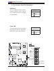
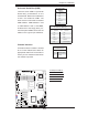
ATX Power Connector
There are a 24-pin main power supply
connector(JPW1) and an 8-pin CPU
PWR connector (JPW3) on the moth-
erboard. These power connectors
meet the SSI EPS 12V specifi cation.
For the 8-pin PWR (JPW3), please
refer to the item listed below.
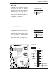
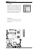
Processor Power Connector
In addition to the Primary ATX power
connector (above), the 12V 8-pin CPU
PWR connector at JPW3 must also
be connected to your power supply.
See the table on the right for pin
defi nitions.
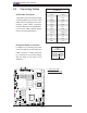
ATX Power 24-pin Connector
Pin Defi nitions
Pin# Defi nition Pin # Defi nition
13 +3.3V 1 +3.3V
14 -12V 2 +3.3V
15 COM 3 COM
16 PS_ON 4 +5V
17 COM 5 COM
18 COM 6 +5V
19 COM 7 COM
20 Res (NC) 8 PWR_OK
21 +5V 9 5VSB
22 +5V 10 +12V
23 +5V 11 +12V
24 COM 12 +3.3V
12V 8-pin Power Con-
nector
Pin Defi nitions
Pins Defi nition
1 through 4 Ground
5 through 8 +12V
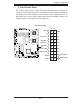
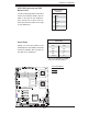
A. 24-pin ATX PWR
B. 8-pin Processor PWR
A
B
JBT
JWOL1
JPL1
JWD
JPG1
JI2C2
JI2C4
JI2C1
JI2C3
J8
JPT1
SPKR
JD1
J18
JP2
JOH1
JL1
JP1
J7
FAN6
FAN5
FAN1
FAN2
FAN3
FAN4
LED5
LED6
LE1
USB6
T-SGPIO2
USB4/5
USB2/3
COM2
LAN2
LAN1
PWR
BANK1
COM1
VGA
USB0/1
BANK2
KB/MS
DIMM1A
DIMM1B
DIMM2A
DIMM2B
CPU2
CPU1
Slot5 PCI-E x8
Slot6 PCI-E x8
Slot7 SIMLP
Slot4 PCI-E x8
Slot1 PCI-X 133MHz
Slot 2 PCI-E x4
Slot 0 PCI-U
I-SATA5
I-SATA4
FLOPPY
I-SATA0
I-SATA2
I-SATA1
I-SATA3
X7DWE
IDE#1
SMB
FP CTRL
JPL2
Super I/O
LAN
CTRL
Intel 5400
North Bridge
Slot3 PCI-E x8
Intel ESB2
South Bridge
BIOS
T-SGPIO1
VGA
CTRL
24-Pin ATX PWR
8-Pin PWR