
User's Manual


Chapter 2: Installation
2-23
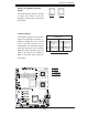
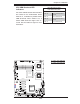
JBT
JWOL1
JPL1
JWD
JPG1
JI2C2
JI2C4
JI2C1
JI2C3
J8
JPT1
SPKR
JD1
J18
JP2
JOH1
JL1
JP1
J7
FAN6
FAN5
FAN1
FAN2
FAN3
FAN4
LED5
LED6
LE1
USB6
T-SGPIO2
USB4/5
USB2/3
COM2
LAN2
LAN1
PWR
BANK1
COM1
VGA
USB0/1
BANK2
KB/MS
DIMM1A
DIMM1B
DIMM2A
DIMM2B
CPU2
CPU1
Slot5 PCI-E x8
Slot6 PCI-E x8
Slot7 SIMLP
Slot4 PCI-E x8
Slot1 PCI-X 133MHz
Slot 2 PCI-E x4
Slot 0 PCI-U
I-SATA5
I-SATA4
FLOPPY
I-SATA0
I-SATA2
I-SATA1
I-SATA3
X7DWE
IDE#1
SMB
FP CTRL
JPL2
Super I/O
LAN
CTRL
Intel 5400
North Bridge
Slot3 PCI-E x8
Intel ESB2
South Bridge
BIOS
T-SGPIO1
VGA
CTRL
24-Pin ATX PWR
8-Pin PWR
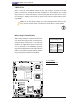
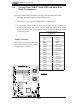
A
A. JI
2
C1
B. JI
2
C2
C. JI
2
C3
D. JI
2
C4
E. VGA Enabled
B
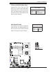
VGA Enable/Disable
JPG1 allows you to enable or disable the
VGA Controller. The default position is on
pins 1 and 2 to use this feature. See the
table on the right for jumper settings.
VGA Enable/Disable
Jumper Settings (JPG1)
Jumper Setting Defi nition
Pins 1-2 Enabled
Pins 2-3 Disabled
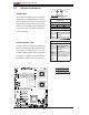
I
2
C Bus to PCI-X/PCI-Exp. Slots
Jumpers JI
2
C1, JI
2
C2, JI
2
C3, and JI
2
C4
allow you to connect the System Man-
agement Bus (I
2
C) to PCI-X and PCI-E
slots. The default setting is Open to dis-
able the connection. See the table on the
right for jumper settings.
I
2
C to PCI-X/PCI/Exp
Jumper Settings
Jumper Setting Defi nition
Closed Enabled
Open Disabled (Default)
C
D
E