SUPER X6DAT-G X6DAi-G USER’S MANUAL Revision 1.
The information in this User’s Manual has been carefully reviewed and is believed to be accurate. The vendor assumes no responsibility for any inaccuracies that may be contained in this document, makes no commitment to update or to keep current the information in this manual, or to notify any person or organization of the updates. Please Note: For the most up-to-date version of this manual, please see our web site at www.supermicro.com.
Preface Preface About This Manual This manual is written for system integrators, PC technicians and knowledgeable PC users. It provides information for the installation and use of the X6DAT-G/X6DAi-G motherboard. Installation and maintenance should be performed by experienced technicians only. The X6DAT-G/X6DAi-G supports single or dual Intel ® Xeon TM EM64T processors at an 800 MHz front side bus speed. Please refer to the motherboard specifications pages on our web site (http://www.supermicro.
X6DAT-G/X6DAi-G User's Manual Table of Contents Preface About This Manual ...................................................................................................... iii Manual Organization ................................................................................................... iii Chapter 1: Introduction 1-1 Overview ......................................................................................................... 1-1 Checklist ...............................................
Table of Contents Chassis Intrusion ................................................................................... 2-13 Universal Serial Bus .............................................................................. 2-13 Fan Headers ........................................................................................... 2-14 Wake-On-Ring ......................................................................................... 2-15 Wake-On-LAN ....................................................
X6DAT-G/X6DAi-G User's Manual Chapter 3: Troubleshooting 3-1 Troubleshooting Procedures ........................................................................ 3-1 Before Power On .................................................................................... 3-1 No Power .................................................................................................. 3-1 No Video ................................................................................................... 3-1 Memory Errors .
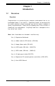
Chapter 1: Introduction 1-1 Introduction Chapter 1 Introduction Overview Checklist Congratulations on purchasing your computer motherboard from an acknowledged leader in the industry. Supermicro boards are designed with the utmost attention to detail to provide you with the highest standards in quality and performance. Check that the following items have all been included with your motherboard. If anything listed here is damaged or missing, contact your retailer.
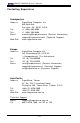
X6DAT-G/X6DAi-G User's Manual Contacting Supermicro Introduction Headquarters Address: Tel: Fax: Email: Web Site: SuperMicro Computer, Inc. 980 Rock Ave. San Jose, CA 95131 U.S.A. +1 (408) 503-8000 +1 (408) 503-8008 marketing@supermicro.com (General Information) support@supermicro.com (Technical Support) www.supermicro.com Europe Address: Tel: Fax: Email: SuperMicro Computer B.V. Het Sterrenbeeld 28, 5215 ML 's-Hertogenbosch, The Netherlands +31 (0) 73-6400390 +31 (0) 73-6416525 sales@supermicro.
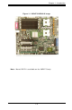
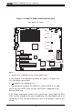
Figure 1-1. X6DAT-G/X6DAi-G Image Note: Marvell SATA is available on the X6DAT-G only.
X6DAT-G/X6DAi-G User's Manual Introduction Figure 1-2.
Chapter 1: Introduction Quick Reference Description Default Setting JBT1 CMOS Clear (See Chapter 2) JK1 Keylock Enable Close (Enabled) JP13 3rd PWR Supply Failure Alarm Enab.
X6DAT-G/X6DAi-G User's Manual Motherboard Features CPU Introduction • Single or dual 604-pin Intel® Xeon TM (EM64T) processors @ 800 MHz front side (system) bus speed. Memory • Eight 184-pin DIMM sockets supporting up to 16 GB ECC registered DDR333 or up to 32 GB ECC registered DDR266 SDRAM Note: Interleaved memory; requires memory modules to be installed in pairs (see Section 2-3 for details).
Chapter 1: Introduction • Microsoft OnNow • Slow blinking LED for suspend state indicator • Main switch override mechanism Onboard I/O • Marvell SATA controller (*X6DAT-G only) • One Intel 8254x Gigabit Ethernet controller (supports 1 GLAN port) • 2 EIDE Ultra DMA/100 bus master interfaces • 1 floppy port interface (up to 2.88 MB) • 1 EPP/ECP Parallel Port • PS/2 mouse and PS/2 keyboard ports • Up to four USB 2.
X6DAT-G/X6DAi-G User's Manual E64MT NOCONA PROCE SSOR#1 DAT A X8 7525E PCI E XP. DDR 266/ 333 1 PCI - X ZCR SL OT J 12 1 PCI - X SL OT J 13 4 DDR I DI MMs I DE UDMA/ 100 HUB BUS 32 BI T / 33 MHz S AT A SATA 0, 1 I CH HANCE RAPI DS PCI X BUS 64 BI T / 66 MHz USB PORT 0, 1, 2, 3 MS. L PC I / O F DD. AC 97 L PC BUS US B H/ W MONI TOR KB. Figure 1-9.
Chapter 1: Introduction Chipset Overview Built upon the functionality and capabilities of the E7525 chipset, the X6DATG/X6DAi-G motherboard provides the performance and feature set required for dual processor-based computer systems, with configuration options optimized for communications, presentation, storage, computation and database applications. The Intel E7525 chipset consists of the following components: the Memory Controller Hub (MCH), and the I/O Controller Hub (6300 ESB ICH).
X6DAT-G/X6DAi-G User's Manual 1-3 Special Features Recovery from AC Power Loss Introduction BIOS provides a setting for you to determine how the system will respond when AC power is lost and then restored to the system. You can choose for the system to remain powered off (in which case you must hit the power switch to turn it back on) or for it to automatically return to a poweron state.
Chapter 1: Introduction CPU Fan Auto-Off in Sleep Mode The CPU fan activates when the power is turned on. It continues to operate when the system enters Standby mode. When in sleep mode, the CPU will not run at full power, thereby generating less heat. CPU Overheat/Fan Fail LED and Control This feature is available when the user enables the CPU overheat/Fan Fail warning function in the BIOS. This allows the user to define an overheat temperature.
X6DAT-G/X6DAi-G User's Manual such as CD-ROMs, network cards, hard disk drives and printers. This also includes consumer devices connected to the PC such as VCRs, TVs, telephones and stereos. Introduction In addition to enabling operating system-directed power management, ACPI provides a generic system event mechanism for Plug and Play and an operating system-independent interface for configuration control.
The SUPER X6DAT-G/X6DAi-G accommodates ATX power supplies. Although most power supplies generally meet the specifications required by the CPU, some are inadequate. You should use one that will supply at least 400W of power. A 12V 8-pin power connection (at J1D1) is required for CPU power consumption, and an additional 12V 4-pin power connection (J32) is also recommended for heavy load configurations.) Also your power supply must supply 1.5A for the Ethernet ports.
X6DAT-G/X6DAi-G User's Manual Introduction 1-14
Chapter 2: Installation Chapter 2 Installation 2-1 Static-Sensitive Devices Electric-Static-Discharge (ESD) can damage electronic components. To prevent damage to your system board, it is important to handle it very carefully. The following measures are generally sufficient to protect your equipment from ESD. Precautions • Use a grounded wrist strap designed to prevent static discharge. • Touch a grounded metal object before removing the board from the antistatic bag.
X6DAT-G/X6DAi-G User's Manual 2-2 Xeon EM64T Processor and Heatsink Installation ! When handling the processor package, avoid placing direct pressure on the label area of the fan. Also, do not place the motherboard on a conductive surface, which can damage the BIOS battery and prevent the system from booting up. IMPORTANT: Always connect the power cord last and always remove it before adding, removing or changing any hardware components.
Chapter 2: Installation 2. Insert the CPU in the socket, making sure that pin 1 of the CPU aligns with pin 1 of the socket (both corners are marked with a triangle). When using only one CPU, install it into CPU socket #1 (socket #2 is automatically disabled if only one CPU is used). Pin 1 3. Press the lever down until you hear the *click*. This means that the CPU is securely installed in the CPU socket. Socket lever in the locking Position Heatsink Installation (*Heatsinks are heavy.
X6DAT-G/X6DAi-G User's Manual Figure 2-1. PGA604 Socket: Empty and with Processor Installed Empty socket Lever ! Warning! Make sure you lift the lever completely when installing the CPU; otherwise, damage to the socket or the CPU may occur. Triangle Processor (installed) Triangle Mounting the Motherboard in the Chassis All motherboards have standard mounting holes to fit different types of chassis. Make sure that the locations of all the mounting holes for both the motherboard and the chassis match.
Chapter 2: Installation 2-3 Installing DIMMs Note: Check the Supermicro web site for recommended memory modules. CAUTION Exercise extreme care when installing or removing DIMM modules to prevent any possible damage. Also note that the memory is interleaved to improve performance (see step 1). DIMM Installation (See Figure 2-2) 1. Insert the desired number of DIMMs into the memory slots, starting with DIMM #1A.
X6DAT-G/X6DAi-G User's Manual To Remove: Use your thumbs to gently push near the edge of both ends of the module. This should release it from the slot. 2-4 I/O Ports/Control Panel Connectors The I/O ports are color coded in conformance with the PC 99 specification. See Figure 2-3 below for the colors and locations of the various I/O ports. Figure 2-3.
Chapter 2: Installation Front Control Panel JF1 contains header pins for various buttons and indicators that are normally located on a control panel at the front of the chassis. These connectors are designed specifically for use with Supermicro server chassis. See Figure 2-4 for the descriptions of the various control panel buttons and LED indicators. Refer to the following section for descriptions and pin definitions. Figure 2-4.
X6DAT-G/X6DAi-G User's Manual 2-5 Connecting Cables ATX Power Supply 24-pin Connector Pin Definitions (J1B4) Pin Number Definition Pin Number Definition 1 +3.3V 13 +3.3V 2 +3.3V 14 -12V 3 COM 15 COM 4 +5V 16 PS_ON# 5 COM 17 COM 6 +5V 18 COM 7 COM 19 COM 8 PWR_OK 20 Res(NC) 9 5VSB 21 +5V 10 +12V 22 +5V 11 +12V 23 +5V 12 +3.3V 24 COM ATX Power Connector There are a 24-pin main power supply connector(PW1:J1B4) and a 4-pin CPU PWR connector (J32) on the board.
Chapter 2: Installation NMI Button NMI Button Pin Definitions (JF1) Pin Number Definition 19 Control 20 Ground The non-maskable interrupt button header is located on pins 19 and 20 of JF1. Refer to the table on the right for pin definitions. Power LED The Power LED connection is located on pins 15 and 16 of JF1. Refer to the table on the right for pin definitions.
X6DAT-G/X6DAi-G User's Manual HDD LED HDD LED Pin Definitions (JF1) The HDD LED connection is located on pins 13 and 14 of JF1. Attach the hard drive LED cable here to display disk activity (for any hard drives on the system, including Serial ATA and IDE). See the table on the right for pin definitions.
Chapter 2: Installation Overheat (OH) LED Pin Definitions (JF1) Overheat/Fan Fail LED Connect an LED to the OH/Fan Fail connection on pins 7 and 8 of JF1 to provide advanced warning of chassis overheating. Refer to the table on the right for pin definitions. Pin Number Definition 7 Vcc 8 GND Overheat/Fan Fail LED State Message Overheat Fan Fail Solid Blink Power Fail LED Power Fail LED Pin Definitions (JF1) The Power Fail LED connection is located on pins 5 and 6 of JF1.
X6DAT-G/X6DAi-G User's Manual Reset Button Reset Pin Definitions (JF1) The Reset Button connection is located on pins 3 and 4 of JF1. Attach it to the hardware reset switch on the computer case. Refer to the table on the right for pin definitions. Pin Number Definition 3 Reset 4 Ground Power Button The Power Button connection is located on pins 1 and 2 of JF1. Momentarily contacting both pins will power on/off the system.
Chapter 2: Installation Chassis Intrusion Chassis Intrusion Pin Definitions (JL1) Pin Number Definition 1 Intrusion Input 2 Ground A Chassis Intrusion header is located at JL1. Attach the appropriate cable to inform you of a chassis intrusion. USB Pin Definition Universal Serial Bus (USB) J40 (Back Panel USB) There are four USB 2.0 (Universal Serial Bus) ports/headers on the motherboard. Two of them are Back Panel USB ports (USB#0-1:J40), and the other two are Front Panel USB headers (USB#2-3:JD2).
X6DAT-G/X6DAi-G User's Manual Fan Headers There are eight fan headers (Fan 1 to Fan 8) on the X6DAT-G/X6DAi-G. See the table on the right for pin definitions. (*Note: These fan headers are 4-pin fan. Pins 1-3 of the fan headers are backward compatible with the traditional 3-pin fans.) *The onboard fan 4-pin Fan Header Pin Definitions (CPU and Chassis Fans ) Pin# 1 2 3 4 Caution: These fan headers use DC power. speed is controlled by Thermal Management via BIOS--Hardware Monitor in the Advanced Setting .
Chapter 2: Installation Wake-On-Ring Wake-on-Ring Pin Definitions (JWOR) The Wake-On-Ring header is designated JWOR. This function allows your computer to be "wakened-up" by an incoming call to the modem when in suspend state. See the table on the right for pin definitions. You must have a Wake-On-Ring card and cable to use this feature.
X6DAT-G/X6DAi-G User's Manual GLAN (Giga-bit Ethernet Port) A G-bit Ethernet port is located beside the COM2 port on the IO backplane. This port accepts RJF1 type cables.
Chapter 2: Installation Power Fault Power Fail Pin Definitions (JP12) Connect a cable from your power supply to the Power Fail header (JP12) to provide a warning of power supply failure. This warning signal is passed through the PWR_LED pin to indicate of a power failure on the chassis. See the table on the right for pin definitions.
X6DAT-G/X6DAi-G User's Manual Overheat LED (JOH1) Table 2-15 Overheat LED Pin Definitions (JOH1) The JOH1 header is used to connect an LED to provide warnings of chassis overheating. Refer to the table on right for pin definitions. Pin Number 1 2 ATX PS/2 Keyboard and PS/2 Mouse Ports Definition OH Active Ground PS/2 Keyboard and Mouse Port Pin Definitions (J9) The ATX PS/2 keyboard and the PS/2 mouse are located at J9. See the table on the right for pin definitions.
Chapter 2: Installation CD-In Header Audio CD Header Pin Definitions (CD1) There is two 4-pin CD headers on the motherboard. This allows you to use the onboard sound for audio CD playback. Connect the audio cables from your CD drive to the header. See the tables at right for pin definitions.
X6DAT-G/X6DAi-G User's Manual SMB Power (I2 C) SMB PWR Pin Definitions (J24) Connector Pin # 1 2 3 4 5 I2 C Connector (J24), located between the PWR ForceOn Header and the PWR Fault header, monitors the status of PWR Supply, Fan and system temperature. Definition Clock Data N/A N/A N/A SMB Header Pin Definitions (J22) SMB Pin Number 1 2 3 4 A System Management Bus header is located at J22. Connect the appropriate cable here to utilize SMB on your system.
Chapter 2: Installation SATA SMB (I2C)(*X6DAT-G only) SATA SMB (JS10) Pin Definitions Pin Definition Number Data 1 Ground 2 Clock 3 A Serial ATA System Management Bus header is located at JS10. Connect the appropriate cable here to use SATA System Management Bus on your system. Serial Ports Serial Port Pin Definitions (COM1, COM2) COM1 (J6) and COM2 (J38) serial ports are located under the parallel port. See the table on the right for pin definitions.
X6DAT-G/X6DAi-G User's Manual 2-6 Jumper Settings Explanation of Jumpers Connector Pins To modify the operation of the motherboard, jumpers can be used to choose between optional settings. Jumpers create shorts between two pins to change the function of the connector. Pin 1 is identified with a square solder pad on the printed circuit board. See the motherboard layout pages for jumper locations.
Chapter 2: Installation CMOS Clear JBT1 is used to clear CMOS. Instead of pins, this "jumper" consists of contact pads to prevent the accidental clearing of CMOS. To clear CMOS, use a metal object such as a small screwdriver to touch both pads at the same time to short the connection. Always remove the AC power cord from the system before clearing CMOS. Note: For an ATX power supply, you must completely shut down the system, remove the AC power cord and then short JBT1 to clear CMOS.
X6DAT-G/X6DAi-G User's Manual Audio Enable/Disable AC97 Enable/Disable Jumper Settings (JPAC) JPAC enables or disables the Audio Connector on the motherboard. No setting in the BIOS is used to activate onboard audio. See the table on the right for jumper settings. The default setting is enabled. Jumper Position 1-2 2-3 Serial ATA Enable (*X6DAT-G Only) Definition Enabled Disabled SATA Enable Jumper Settings (JPS1) Jumper Position 1-2 2-3 JPS1 allows you to enable Marvell SATA Controller.
Chapter 2: Installation 3rd Power Supply Alarm Enable/Disable 3rd Power Supply Alarm Enable Jumper Settings (JP13) Jumper Definition Position Enabled Open Disabled Closed The system can notify you in the event of the 3rd power supply failure. Use this feature when three power supply units are installed in the chassis with one acting as a backup. If you only have one or two power supply units installed, you should disable this (the default setting) with JP13 to prevent false alarms.
X6DAT-G/X6DAi-G User's Manual Reboot Option Enable (*For Debug only) Reboot Option Enable Jumper Settings (JP15) Enabling the reboot option with JP15 will cause the system to reboot after a timeout if the system hangs on bootup. See the table on the right for pin definitions. The default setting is enabled.
Chapter 2: Installation 2-7 Onboard Indicators Left Right GLAN LEDs 1 Gb LAN Right LED Indicator (Speed LED) The Gigabit Ethernet LAN ports has two LEDs. The yellow LED indicates activity while the other LED may be green, orange or off to indicate the speed of the connection. See the table at right for the functions associated with the second LED.
X6DAT-G/X6DAi-G User's Manual Pre-LED Indicators Pre-LED Indicators (DS1, DS2, DS3, DS4) No. State Definition DS1 DS2 Stay On HDD DS3 Present DS4 There are four Pre-LEDs (DS1, DS2, DS3, DS4) on the motherboard. A Pre-LED will stay on to indicate the presence of a hard drive. See the table on the right for the pin definitions.
Chapter 2: Installation 2-8 Parallel Port, Floppy/ and Hard Disk Drive Connections Note the following when connecting the floppy and hard disk drive cables: • The floppy disk drive cable has seven twisted wires. • A red mark on a wire typically designates the location of pin 1. • A single floppy disk drive ribbon cable has two connectors to provide for two floppy disk drives.
X6DAT-G/X6DAi-G User's Manual Floppy Connector Floppy Connector Pin Definitions (J8) The floppy connector is located at JP8. See the table below for pin definitions.
Chapter 3: Troubleshooting Chapter 3 Troubleshooting 3-1 Troubleshooting Procedures Use the following procedures to troubleshoot your system. If you have followed all of the procedures below and still need assistance, refer to the ‘Technical Support Procedures’ and/or ‘Returning Merchandise for Service’ section(s) in this chapter. Note: Always disconnect the power cord before adding, changing or installing any hardware components. Before Power On 1.
X6DAT-G/X6DAi-G User's Manual NOTE If you are a system integrator, VAR or OEM, a POST diagnostics card is recommended. For I/O port 80h codes, refer to App. B. Memory Errors 1. Make sure that the DIMM modules are properly and fully installed. 2. Determine if different speeds of DIMMs have been installed and verify that the BIOS setup is configured for the fastest speed of RAM used. It is recommended to use the same RAM speed for all DIMMs in the system. 3.
Chapter 3: Troubleshooting 1. Please go through the ‘Troubleshooting Procedures’ and 'Frequently Asked Question' (FAQ) sections in this chapter or see the FAQs on our web site (http://www.supermicro.com/support/faqs/) before contacting Technical Support. 2. BIOS upgrades can be downloaded from our web site at (http://www.supermicro.com/support/bios/). Note: Not all BIOS can be flashed depending on the modifications to the boot block code. 3.
X6DAT-G/X6DAi-G User's Manual than your BIOS before downloading. Note: There is no BIOS recovery function available for the motherboard. Should a problem occur after you flash the BIOS, you will need to change the BIOS chip. Question: What's on the CD that came with my motherboard? Answer: The supplied compact disc has quite a few drivers and programs that will greatly enhance your system. We recommend that you review the CD and install the applications you need.
Chapter 4: Phoenix BIOS Chapter 4 Phoenix BIOS 4-1 Introduction This chapter describes the Phoenix BIOS™ Setup utility for the X6DAT-G/ X6DAi-G. The Phoenix ROM BIOS is stored in a flash chip and can be easily upgraded using a floppy disk-based program. Note: Due to periodic changes to the BIOS, some settings may have been added or deleted and might not yet be recorded in this manual. Please refer to the Manual Download area of the Supermicro web site
X6DAT-G/X6DAi-G User's Manual 4-2 Running Setup *Default settings are in bold text unless otherwise noted. The BIOS setup options described in this section are selected by choosing the appropriate text from the main BIOS Setup screen. All displayed text is described in this section, although the screen display is often all you need to understand how to set the options (see on next page). When you first power on the computer, the Phoenix BIOS™ is immediately activated.
Chapter 4: Phoenix BIOS Main BIOS Setup Menu Main Setup Features System Time To set the system date and time, key in the correct information in the appropriate fields, or use "-" and "+" to change the Hour, Minute and Second fields. System Date Use the arrow keys to highlight the month, day and year fields and enter the correct data. BIOS Date This section allows the BIOS to automatically display the BIOS date code. The BIOS date code is used to identify the BIOS release date/release version.
X6DAT-G/X6DAi-G User's Manual Legacy Diskette A This setting allows the user to set the type of floppy disk drive installed as diskette A. The options are Disabled, 360Kb 5.25 in, 1.2MB 5.25 in, 720Kb 3.5 in, 1.44/1.25MB, 3.5 in and 2.88MB 3.5 in. Parallel ATA This setting allows the user to choose the function of IDE channels. The options are Disabled, Channel 0, Channel 1 and Both. Serial ATA This setting allows the user to enable or disable the function of Serial ATA.
Chapter 4: Phoenix BIOS Type Type This feature allows the user to select the type of IDE hard drives. The option- "User" will allow the user to enter the parameters of the HDD installed at this connection. The option-"Auto" will allow the BIOS to automatically configure the parameters of the HDD installed at the connection. Choose the option"1-39" to select a pre-determined HDD type. Select CD-ROM if a CD-ROM drive is installed. Select ATAPI if a removable disk drive is installed.
X6DAT-G/X6DAi-G User's Manual Transfer Mode This feature allows the user to select transfer mode. The options are Standard, Fast PIO1, Fast PIO2, Fast PIO3, Fast PIO4, FPIO3/DMA1 and FPIO4/DMA2. Ultra DMA (Direct Memory Access) Mode This feature allows the user to select Ultra DMA Modes. DMA Modes allow peripheral devices (such as sound cards, floppy disks) transfer data directly to and from memory without going through the CPU.
Chapter 4: Phoenix BIOS 4-4 Advanced Setup Choose Advanced from the Phoenix BIOS Setup Utility main menu with the arrow keys. You should see the following display. The items with a triangle beside them have sub menus that can be accessed by highlighting the item and pressing . Options for PIR settings are displayed by highlighting the setting option using the arrow keys and pressing . All Advanced BIOS Setup options are described in this section.
X6DAT-G/X6DAi-G User's Manual ACPI Mode Use the setting to determine if you want to employ ACPI (Advanced Configuration and Power Interface) power management on your system. The options are Yes and No. ACPI Sleep Mode This feature allows the user to select the sleep mode for ACPI. The options are S1(-Stanby) and S3 (-Suspend to RAM). Power Button Behavior This setting allows you to choose how the system powers down when the user presses the power button.
Chapter 4: Phoenix BIOS to enable this function, and the area designated will be reserved for the BIOS ROM access only. Select "Uncached" to disable this function and make this area available for other devices. Cache Video BIOS Area This setting allows you to designate a reserve area in the system memory to be used as a Video BIOS buffer to allow the BIOS to write (cache) its data into this reserved memory area.
X6DAT-G/X6DAi-G User's Manual Cache Extended Memory If enabled, this feature will allow the data stored in the extended memory area to be cached (written) into an area in the Static DRAM or written into L1, L2, L3 cache inside the CPU to speed up CPU operation. Select "Uncached" to disable this function. Select "Write Through" to allow data to be cached into the buffer and be written into the system memory at the same time.
Chapter 4: Phoenix BIOS Latency Timer This setting allows you to set the clock rate for Bus Master. A highpriority, high-throughout device may benefit from a greater Clock rate. The options are Default, 0020h, 0040h, 0060h, 0080h, 00A0h, 00C0h, and 00E0h. For Unix, Novell and other Operating Systems, please select the option: "other". If a drive fails after the installation of a new software , you might want to change this setting and try again. Different OS requires different Bus Master clock rate.
X6DAT-G/X6DAi-G User's Manual Clock Spectrum Feature If "Enabled", the Phoenix BIOS will detect and attempt to reduce the Electromagnetic Interference caused by the components. The options are Enabled and Disabled. DRAM Data Integrity Mode If enabled, this feature allows the data stored in the DRAM memory to be ECC (Error Checking & Correction) compliant . The options are 72-bit ECC, 144-bit ECC, Auto and Disabled.
Chapter 4: Phoenix BIOS Advanced Processor Options Access the submenu to make changes to the following settings. CPU Speed This is a display that indicates the speed of the installed processor. Hyper Threading This setting allows you to Enable or Disable the function of Hyper Threading. Enabling hyper-threading results in increased CPU performance. Machine Checking This setting allows you to Enable or Disable Machine Checking.
X6DAT-G/X6DAi-G User's Manual I/O Device Configuration Access the submenu to make changes to the following settings: KBC Clock input This setting allows you to set the clock frequency for the Keyboard Clock. The options are 6MHz, 8MHz, and 12 MHz. Onboard COM1 This setting allows you to assign control of Onboard COM1. The options are Enabled (user defined), Disabled, Auto (BIOS controlled) and OS Controlled. Base I/O Address This feature allows the user to select the base I/O address for Onboard COM1.
Chapter 4: Phoenix BIOS Interrupt This feature allows the user to select the IRQ (interrupt request) for Onboard COM2. The options are IRQ3 and IRQ4. Parallel Port This setting allows you to assign control of the parallel port. The options are Enabled (user defined), Disabled and Auto (BIOS controlled). Base I/O Address This feature allows the user to select the base I/O address for the parallel port. The options are 378, 278 and 3BC.
X6DAT-G/X6DAi-G User's Manual DMI Event Logging Access the submenu to make changes to the following settings. Event Log Validity This is a display, not a setting, informing you of the event log validity. Event Log Capacity This is a display, not a setting, informing you of the event log capacity. View DMI Event Log Highlight this item and press to view the contents of the event log. Event Logging This setting allows you to Enable or Disable event logging.
Chapter 4: Phoenix BIOS Console Redirection Access the submenu to make changes to the following settings. COM Port Address This feature allows the user to specify whether to redirect the console to On-board COM A or On-board COM B. This setting can also be Disabled. BAUD Rate This feature allows the user to select the BAUD rate for console redirection. The options are 300, 1200, 2400, 9600, 19.2K, 38.4K, 57.6K and 115.2K.
X6DAT-G/X6DAi-G User's Manual Hardware Monitor Logic CPU Temperature Threshold This option allows the user to set a CPU temperature threshold that will activate the alarm system when the CPU temperature reaches this pre-set temperature threshold. The options are 85 oC, 90 o C, 95oC and 100oC. Highlight this and hit to see monitor data for the following items: CPU1 Temperature: This item displays CPU1 Temperature. CPU2 Temperature: This item displays CPU2 Temperature.
Chapter 4: Phoenix BIOS 4-5 Security Choose Security from the Phoenix BIOS Setup Utility main menu with the arrow keys. You should see the following display. Security setting options are displayed by highlighting the setting using the arrow keys and pressing . All Security BIOS settings are described in this section. Supervisor Password Is: This feature allows the BIOS to show whether a supervisor password has been entered for the system.
X6DAT-G/X6DAi-G User's Manual Set Supervisor Password When the item "Set Supervisor Password" is highlighted, hit the key. When prompted, type the Supervisor's password in the dialogue box to set or to change supervisor's password, which allows access to the BIOS. Set User Password When the item "Set User Password" is highlighted, hit the key. When prompted, type the user's password in the dialogue box to set or to change the user's password, which allows access to the system at bootup.
Chapter 4: Phoenix BIOS 4-6 Boot Choose Boot from the Phoenix BIOS Setup Utility main menu with the arrow keys. You should see the following display. Highlighting a setting with a + or - will expand or collapse that entry. See details on how to change the order and specifications of boot devices in the Item Specific Help window. All Boot BIOS settings are described in this section. +Removable Devices Highlight and press to expand the field.
X6DAT-G/X6DAi-G User's Manual 4-7 Exit Choose Exit from the Phoenix BIOS Setup Utility main menu with the arrow keys. You should see the following display. All Exit BIOS settings are described in this section. Exit Saving Changes Highlight this item and hit to save any changes you've made and to exit the BIOS Setup utility. Exit Discarding Changes Highlight this item and hit to exit the BIOS Setup utility without saving any changes you may have made.
Chapter 4: Phoenix BIOS Discard Changes Highlight this item and hit to discard (cancel) any changes you've made. You will remain in the Setup utility. Save Changes Highlight this item and hit to save any changes you've made. You will remain in the Setup utility.
X6DAT-G/X6DAi-G User's Manual Notes 4-24
Appendix A: BIOS POST Codes Appendix A BIOS POST Codes This section lists the POST (Power On Self Test) codes for the PhoenixBIOS. POST codes are divided into two categories: recoverable and terminal. Recoverable POST Errors When a recoverable type of error occurs during POST, the BIOS will display an POST code that describes the problem.
X6DAT-G/X6DAi-G User's Manual POST Code 18h 1Ah 1Ch 20h 22h 24h 28h 29h 2Ah 2Ch 2Eh 2Fh 32h 33h 36h 38h 3Ah 3Ch 3Dh 41h 42h 45h 46h 47h 48h 49h 4Ah 4Bh 4Ch 4Eh 4Fh 50h 51h 52h 54h 55h 58h 59h 5Ah 5Bh Description 8254 timer initialization 8237 DMA controller initialization Reset Programmable Interrupt Controller 1-3-1-1 Test DRAM refresh 1-3-1-3 Test 8742 Keyboard Controller Set ES segment register to 4 GB Auto size DRAM Initialize POST Memory Manager Clear 512 kB base RAM 1-3-4-1 RAM failure on address li
Appendix A: BIOS POST Codes POST Code 5Ch 60h 62h 64h 66h 67h 68h 69h 6Ah 6Bh 6Ch 6Eh 70h 72h 76h 7Ch 7Dh 7Eh 80h 81h 82h 83h 84h 85h 86h 87h 88h 89h 8Ah 8Bh 8Ch 8Fh 90h 91h 92h 93h 95h 96h 97h 98h Description Test RAM between 512 and 640 kB Test extended memory Test extended memory address lines Jump to UserPatch1 Configure advanced cache registers Initialize Multi Processor APIC Enable external and CPU caches Setup System Management Mode (SMM) area Display external L2 cache size Load custom defaults (op
X6DAT-G/X6DAi-G User's Manual POST Code 99h 9Ah 9Ch 9Dh 9Eh 9Fh A0h A2h A4h A8h AAh ACh AEh B0h B1h B2h B4h B5h B6h B7h B9h BAh BBh BCh BDh BEh BFh C0h C1h C2h C3h C4h C5h C6h C7h C8h C9h CAh CBh CCh Description Check for SMART Drive (optional) Shadow option ROMs Set up Power Management Initialize security engine (optional) Enable hardware interrupts Determine number of ATA and SCSI drives Set time of day Check key lock Initialize typematic rate Erase F2 prompt Scan for F2 key stroke Enter SETUP Clear Bo
Appendix A: BIOS POST Codes POST Code CDh CEh D2h Description Re-map I/O and memory for PCMCIA Initialize digitizer and display message Unknown interrupt The following are for boot block in Flash ROM POST Code E0h E1h E2h E3h E4h E5h E6h E7h E8h E9h EAh EBh ECh EDh EEh EFh F0h F1h F2h F3h F4h F5h F6h F7h Description Initialize the chipset Initialize the bridge Initialize the CPU Initialize system timer Initialize system I/O Check force recovery boot Checksum BIOS ROM Go to BIOS Set Huge Segment Initiali
X6DAT-G/X6DAi-G User's Manual Notes A-6
Appendix B: Software Installation Appendix B Installing Software Drivers and Windows Operating System After all the hardware has been installed, you must first configure the Adaptec Embedded Serial ATA RAID Driver before you install the Windows operating system. The necessary drivers are all included on the Supermicro bootable CDs that came packaged with your motherboard. (For the information on Adaptec's SATA HostRAID Utility based on Marvell's chip, please refer to Appendix C.
X6DAT-G/X6DAi-G User's Manual To configure SATA RAID for Operating Systems that support RAID functions(--Windows, Red Hat & SuSe, Linux) 1. Select "Main Setup Setting" from the Phoenix BIOS menu and set "SATA RAID Enable" to Enable. (The Defualt setting is Disabled.) 3. Go to the "Exit" menu and select "Save and Exit". Hit the key to save the change and exit the Phoenix BIOS. 4. Press for Adaptec RAID Configuration Utility.
Appendix B: Software Installation Using the Adaptec RAID Configuration Utility (ARC) The Adaptec RAID Configuration Utility is an embedded BIOS Utility, including: *Array Configuration Utility: Use this utility when you want to create, configure and manage arrays. * Disk Utilities: Use this option to format or verify disks.
X6DAT-G/X6DAi-G User's Manual Managing Arrays Select this option to view array properties, and delete arrays. The following sections describe the operations Of "Managing Arrays". To select this option, use the arrow keys and the key to select "Managing Arrays" from the main menu (as shown above).
Appendix B: Software Installation Viewing Array Properties To view the properties of an existing array: 1. At the BIOS prompt, press Ctrl+A. 2. From the ARC menu, select Array Configuration Utility (ACU). 3. From the ACU menu, select Manage Arrays (as shown on the previous screen.) 4. From the List of Arrays dialog box, select the array you want to view and press Enter. The Array Properties dialog box appears, showing detailed information on the array.
X6DAT-G/X6DAi-G User's Manual Creating Arrays Before creating arrays, make sure the disks for the array are connected and installed in your system. Note that disks with no usable space, or disks that are un-initialized are shown in gray and cannot be used. See Initializing Disk Drives. To create an array: 1 Turn on your computer and press Ctrl+A when prompted to access the ARC utility. 2 From the ARC menu, select Array Configuration Utility Main Menu (ACU) (as shown on the first screen on page B-5).
Appendix B: Software Installation 5 Press Enter when both disks for the new array are selected. The Array Properties menu displays (as the screen shown below). Assigning Array Properties Once you've create a new array, you are ready to assign the properties to the array. *Caution: Once the array is created and its properties are assigned, you cannot change the array properties using the ACU. You will need to use the Adaptec Storage Manager - Browser Edition.
X6DAT-G/X6DAi-G User's Manual 2. Under the item "Arrays Label", type in an label and press Enter. (*Note: The label shall not be more than 15 characters.) 3. For RAID 0, select the desired stripe size. (*Note: Available stripe sizes are 16, 32, and 64 KB-default. It is recommended that you do not change the default setting.) 4. The item: "Create RAID via" allows you to select between the different creating methods for RAID 0 and RAID 1. The following table gives examples of when each is appropriate.
Appendix B: Software Installation 5. When you are finished, press Done (as the screen shown below). Notes: 1. Before adding a new drive to an array, back up any data contained on the new drive. Otherwise, all data will be lost. 2. If you stop the Build or Clear process on a RAID 1 from ACU, you can restart it by pressing Ctrl+R. 3. A RAID 1 created using the Quick Init option may return some data miscompares if you later run a consistency check. This is normal and is not a cause for concern. 4.
X6DAT-G/X6DAi-G User's Manual Adding a Bootable Array To make an array bootable: 1. From the Main menu, select Manage Arrays. 2. From the List of Arrays, select the array you want to make bootable, and press Ctrl+B. 3. Enter Y to create a bootable array when the following message is displayed: "This will make all other existing bootable array non-bootable. Do you want to make this array bootable? (Yes/No):" Then, a bootable array will be created.
Appendix B: Software Installation Initializing Disk Drives If an installed disk does not appear in the disk selection list for creating a new array, or if it appears grayed out, you may have to initialize it before you can use it as part of an array. Drives attached to the controller must be initialized before they can be used in an array. Caution: Initializing a disk overwrites the partition table on the disk and makes any data on the disk inaccessible.
X6DAT-G/X6DAi-G User's Manual 4. Use the up and down arrow keys to highlight the disk you wish to initialize and press Insert (as shown in the screen below).
Appendix B: Software Installation 5. Repeat Step 4 so that both drives to be initialized are selected (as shown in the screen below). 6. Press Enter. 7. Read the warning message as shown in the screen. 8. Make sure that you have selected the correct disk drives to initialize. If correct, type Y to continue.
X6DAT-G/X6DAi-G User's Manual Rebuilding Arrays *Note 1: Rebuilding applies to Fault Tolerant array (RAID 1) only. If an array Build process (or initialization) is interrupted or critical with one member missing, you must perform a Rebuild to get the array to Optimal status. For a critical array Rebuild operation, the optimal drive is the source drive. *Note 2: If no spare array exists and a hard disk drive fails, you need to create a spare before you can rebuild an array.
Appendix B: Software Installation Using the Disk Utilities The Disk Utilities enable you to format or verify the media of your Serial ATA hard disks. To access the disk utilities: 1. Turn on your computer and press Ctrl+A when prompted to access the ARC utility (as shown in the screen below.
X6DAT-G/X6DAi-G User's Manual 2. From the ARC menu, select Disk Utilities as shown in the screen below. 3 Select the desired disk and press Enter (as shown in the screen below.
Appendix B: Software Installation You can choose from the following options: 1. Format Disk—Simulates a low-level format of the hard drive by writing zeros to the entire disk. Serial ATA drives are low-level formatted at the factory and do not need to be low-level formatted again. (*Caution: Formatting destroys all data on the drive. Be sure to back up your data before performing this operation.) 2. Verify Disk Media—Scans the media of a disk drive for defects.
X6DAT-G/X6DAi-G User's Manual B-2 Installing Intel's ESB6300 (Hance Rapids) Driver by Adaptec and the Windows OS a. Insert Supermicro's bootable CD that came with the package into the CD Drive during the system reboot, and the screen:"Super Micro Driver Diskette Maker" will appear. b. From the list displayed on the screen, choose the item: "Intel Hance Rapids Driver by 3rd Party (Adaptec)" and press . c. From the next screen displayed, choose the OS driver you want to install and press . d.
Appendix B: Software Installation B-3 Installing Other Software Programs and Drivers A. Installing Drivers other than Adaptec Embedded Serial ATA RAID Controller Driver After you've installed Windows Operating System, a screen as shown below will appear. You are ready to install software programs and drivers that have not yet been installed. To install these software programs and drivers, click the icons to the right of these items.
X6DAT-G/X6DAi-G User's Manual Supero Doctor III The Supero Doctor III program is a Web base management tool that supports remote management capability. It includes Remote and Local Management tools. The local management is called SD III Client. The Supero Doctor III program included on the CDROM that came with your motherboard allows you to monitor the environment and operations of your system. Supero Doctor III displays crucial system information such as CPU temperature, system voltages and fan status.
Appendix B: Software Installation Supero Doctor III Interface Display Screen-II (Remote Control) (*Note: SD III Software Revision 1.0 can be downloaded from our Web site at: ftp://ftp.supermicro.com/utility/Supero_Doctor_III/. You can also download SDIII User's Guide at: http://www.supermicro.com/PRODUCT/ Manuals/SDIII/UserGuide.pdf. For Linux, we will still recommend Supero Doctor II.
X6DAT-G/X6DAi-G User's Manual Notes B-22
Appendix C: Software Installation: Adaptec's SATA HostRAID Utility Appendix C Software Installation: Adaptec's SATA HostRAID Utility for Marvell's 88SX6041 Chip (*For X6DAT-G only.) After all the hardware has been installed, you must first configure Adaptec's Serial ATA RAID Driver (*Note) before you install the Windows operating system, and other software drivers. The necessary drivers are all included on the Supermicro CDs that came packaged with your motherboard.
X6DAT-G/X6DAi-G User's Manual Operating Systems supported by the SATA RAID Host Controller Microsoft *Windows® 2000, Windows Server ® 2003, and Windows XP Linux *Red Hat 8.0 and 9.0 *SuSE 8.1 and 8.
Appendix C: Software Installation: Adaptec's SATA HostRAID Utility 8. When the Adaptec Embedded Serial ATA HostRAID driver is found, press Enter. Follow the remaining on-screen instructions to complete your installation. Installing the Driver in an Existing Windows System Please follow the steps listed below to install a driver in a system that already has a Windows operating system: 1. Create a driver disk by following the instructions from the Web site or the product CD. 2. Start Windows.
X6DAT-G/X6DAi-G User's Manual Installing the SuSE 8.1 or 8.2 Driver in a New Linux System 1. Obtain a driver disk from either the Web site or the product CD. 2. Restart the computer. 3. If creating an array, press Ctrl-A when prompted to enter the ARC utility. For instructions on creating an array from the BIOS, see the section"Adaptec RAID Configuration Utility". For a simple volume, skip to Step 4. 4.
Appendix C: Software Installation: Adaptec's SATA HostRAID Utility C-3 Installing Adaptec Storage Management A. Browser Edition Overview This chapter discusses the installation procedure for installing Adaptec Storage Manager – Browser Edition to enable remote and local management of arrays. Browsers supported: To run Adaptec Storage Manager – Browser Edition, your computer must have a Web browser supporting JavaScript and cookies only.
X6DAT-G/X6DAi-G User's Manual B. On Windows **Note: When installing on a FAT 32 file system, the folder being installed is automatically hidden.) To install Adaptec Storage Manager – Browser Edition 1. Verify that a supported browser is installed. See the section-"Supported Browsers" for details. 2. Insert the product installation CD and wait for the Autorun executable to start the installation. If this does not occur, browse the CD and click Autorun. 3. Click Adaptec Utilities. 4.
Appendix C: Software Installation: Adaptec's SATA HostRAID Utility Configuring Internet Explorer for Local Management When using the High security setting, you must enable the following settings manually: * JavaScript * Cookies (not stored) You do not need to enable the following custom level security settings for the local Intranet in Internet Explorer 5 and 5.5.
X6DAT-G/X6DAi-G User's Manual 6. You are now ready to proceed to C-4-"Using Adaptec Storage Manager – Browser Edition". Configuring Netscape Navigator for Remote Management If you know the IP address of the system you want to manage remotely: 1. Choose Edit> Preferences > Advanced> Proxies > Manual proxy configuration > No Proxy For. 2. Type the managed system’s IP address. To install Adaptec Storage Manager on Linux (*Note: When performing this installation, keep in mind that Linux is case sensitive.
Appendix C: Software Installation: Adaptec's SATA HostRAID Utility C-4.Using Adaptec Storage Manager(-Browser Edition) Overview This chapter describes how to use Adaptec Storage Manager – Browser Edition to manage arrays. (*Note: Your controller may not support all of the features described. In most cases if a feature is not supported by your controller, the feature does not appear in the interface.
X6DAT-G/X6DAi-G User's Manual Logging In To login: 1. Start Adaptec Storage Manager – Browser Edition. * In Windows, click Start > Programs > Adaptec Storage Manager > Adaptec Storage Manager – Browser Edition. * In Linux, click Start > System > Adaptec Storage Manager. The Login screen appears. 2. Enter the host name or IP address of the system you want to manage and the username and password you would use to log into that system. 3. Click Login.
Appendix C: Software Installation: Adaptec's SATA HostRAID Utility Installing a Security Certificate If you chose not to install a security certificate when you installed Adaptec Storage Manager – Browser Edition, you must install the certificate when you run the application for the first time. To create the certificate: 1. When the Security Alert window appears, click View Certificate. 2. On the Certificate window, click Install Certificate. 3. On the Certificate Import wizard window, click Next.
X6DAT-G/X6DAi-G User's Manual The action buttons are: * Logout—Selecting Logout ends your session and returns you to the Login screen. * Rescan—Used to rescan the configuration of the system. Typically, when a rescan is required, it occurs automatically; for example, after an array is created. However, the system configuration can change without Adaptec Storage Manager being notified.
Appendix C: Software Installation: Adaptec's SATA HostRAID Utility Physical Devices The Physical Devices view displays information about the drives and enclosures attached to the Adaptec RAID controller. The devices are shown organized by the channel or port that they are connected to and shown in numerical order. The display for each channel includes information on maximum speed capability, the number of the channel on the controller, and the number of devices found (excluding the SCSI controller).
X6DAT-G/X6DAi-G User's Manual When expanded, the Full Size Capacity View button and the Relative Size Capacity View button represent each drive as a bar. A drive that is not used as part of any array is shaded blue surrounded by a dotted line. displays a full-length bar for each drive, regardless of capacity. displays a bar for each drive, with the largest capacity drive full-length and the other drives proportional to the drive capacity, relative to the largest drive.
Appendix C: Software Installation: Adaptec's SATA HostRAID Utility If a global hot spare exists, all arrays that the hot spare is large enough to protect will show as protected. In the expanded view, the icons for the arrays are arranged vertically and alongside them are the capacity, name, and type of array. Selecting an array by clicking on it will highlight the following in amber: * All the drives or segments that form the array in the Physical Devices view.
X6DAT-G/X6DAi-G User's Manual C-5 Adaptec RAID Configuration Utility The Array Configuration Utility (ACU) enables you to create, manage, and delete arrays from the controller’s BIOS, and initialize drives. A. Managing Arrays Select the Manage Arrays option to view array properties and members, and delete arrays. The following sections describe these operations in greater detail. Viewing Array Properties To view the properties of an existing array: 1. At the BIOS prompt, press Ctrl+A. 2.
Appendix C: Software Installation: Adaptec's SATA HostRAID Utility B. Creating Arrays Before creating arrays, make sure the disks for the array are connected and installed in your system. Note that disks with no usable space, or disks that are not initialized are shown in gray and cannot be used. See Initializing Disk Drives. To create an array 1. Turn on your computer and press Ctrl+A when prompted to access the ARC utility. 2. From the ARC menu, select Array Configuration Utility (ACU). 3.
X6DAT-G/X6DAi-G User's Manual (*Notes:) * Before adding a new drive to an array, back up any data contained on the new drive. Otherwise, all data will be lost. * If you stop the Build or Clear process on a RAID 1 from ACU you can only restart it from Adaptec Storage Manager -Browser Edition. (See C-4 for details.) * A RAID 1 created using the Quick Init. Option may return some data if you later run a consistency check. This is normal and is not a cause for concern.
Appendix C: Software Installation: Adaptec's SATA HostRAID Utility Using the Disk Utilities The Disk Utilities enable you to format or verify the media of your Serial ATA hard disks. To access the disk utilities: 1. Turn on your computer and press Ctrl+A when prompted to access the ARC utility. 2. From the ARC menu, select Disk Utilities. 3. Select the desired disk and press Enter.
X6DAT-G/X6DAi-G User's Manual Notes C-20