AS1021M-T2 AS1021M-82 USER’S MANUAL 1.
The information in this User’s Manual has been carefully reviewed and is believed to be accurate. The vendor assumes no responsibility for any inaccuracies that may be contained in this document, makes no commitment to update or to keep current the information in this manual, or to notify any person or organization of the updates. Please Note: For the most up-to-date version of this manual, please see our web site at www.supermicro.com.
Preface Preface About This Manual This manual is written for professional system integrators and PC technicians. It provides information for the installation and use of the AS1021M-T2/1021M-82. Installation and maintainance should be performed by experienced technicians only.
AS1021M-T2/1021M-82 User's Manual Chapter 4: System Safety You should thoroughly familiarize yourself with this chapter for a general overview of safety precautions that should be followed when installing and servicing the AS1021M-T2/1021M-82. Chapter 5: Advanced Serverboard Setup Chapter 5 provides detailed information on the H8DMR-i2/H8DMR-82 serverboard, including the locations and functions of connections, headers and jumpers.
Preface Notes v
AS1021M-T2/1021M-82 User's Manual Table of Contents Preface About This Manual ...................................................................................................... iii Manual Organization ................................................................................................... iii Chapter 1: Introduction 1-1 Overview ......................................................................................................... 1-1 1-2 Serverboard Features ..........................
Table of Contents Chapter 4: System Safety 4-1 Electrical Safety Precautions ........................................................................... 4-1 4-2 General Safety Precautions ............................................................................. 4-2 4-3 ESD Precautions ............................................................................................ 4-3 4-4 Operating Precautions ....................................................................................
AS1021M-T2/1021M-82 User's Manual Overheat LED ........................................................................................ 5-17 Wake-On-LAN ........................................................................................ 5-18 Wake-On-Ring ......................................................................................... 5-18 PWR I2C ................................................................................................. 5-18 IPMB ........................................
Table of Contents 6-5 Power Supply................................................................................................... 6-9 Power Supply Failure ................................................................................ 6-9 Removing/Replacing the Power Supply .................................................... 6-9 Chapter 7: BIOS 7-1 Introduction ...................................................................................................... 7-1 7-2 Main Menu ...............
AS1021M-T2/1021M-82 User's Manual Notes x
Chapter 1: Introduction Chapter 1 Introduction 1-1 Overview The AS1021M-T2/1021M-82 is a 1U server comprised of two main subsystems: the SC815TQ+-560/SC815S+-560 server chassis and the H8DMR-i2/H8DMR-82 dual processor serverboard. Please refer to our web site for information on operating systems that have been certified for use with the AS1021M-T2/1021M-82 (www. supermicro.com/aplus).
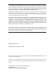
AS1021M-T2/1021M-82 User's Manual One (1) CD containing drivers and utilities SuperServer AS1021M-T2/1021M-82 User's Manual 1-2 Serverboard Features At the heart of the AS1021M-T2/1021M-82 lies the H8DMR-i2/H8DMR-82, a dual processor serverboard based on nVidia's MCP55 Pro chipset. Below are the main features of the H8DMR-i2/H8DMR-82 (see Figure 1-1 for a block diagram of the chipset). Processors The H8DMR-i2/H8DMR-82 supports single or dual AMD Socket F type processors.
Chapter 1: Introduction PCI Expansion Slots The H8DMR-i2/H8DMR-82 has two Universal PCI slots, each of which support either one x8 PCI-Express slots or one PCI-X 133/100 MHz slot. One standard size PCI-X or PCI-Express x8 add-on card and one low profile PCI-X add-on card (all with riser cards) may be used with the server. Onboard Controllers/Ports One floppy drive controller one onboard ATA/100 controller are provided to support up to two IDE hard drives or ATAPI devices.
AS1021M-T2/1021M-82 User's Manual SATA/SCSI Subsystem The SC815TQ+-560/SC815S+-560 chassis was designed to support four SATA (1021M-T2) or SCSI (1021M-82) hard drives, which are hot-swappable units. Note: The operating system you use must have RAID support to enable the hot-swap capability of the SATA/SCSI drives. PCI Expansion Slots One standard size and one low-profile PCI-X/PCI-E add-on card may be used with the SC815TQ+-560/SC815S+-560 chassis.
Chapter 1: Introduction Figure 1-1. nVidia MCP55 Pro Chipset: System Block Diagram Note: This is a general block diagram. Please see Chapter 5 for details.
AS1021M-T2/1021M-82 User's Manual 1-4 Contacting Supermicro Headquarters Address: Tel: Fax: Email: Web Site: SuperMicro Computer, Inc. 980 Rock Ave. San Jose, CA 95131 U.S.A. +1 (408) 503-8000 +1 (408) 503-8008 marketing@supermicro.com (General Information) support@supermicro.com (Technical Support) www.supermicro.com Europe Address: Tel: Fax: Email: SuperMicro Computer B.V. Het Sterrenbeeld 28, 5215 ML 's-Hertogenbosch, The Netherlands +31 (0) 73-6400390 +31 (0) 73-6416525 sales@supermicro.
Chapter 2: Server Installation Chapter 2 Server Installation 2-1 Overview This chapter provides a quick setup checklist to get your AS1021M-T2/1021M-82 up and running. Following these steps in the order given should enable you to have the system operational within a minimum amount of time. This quick setup assumes that your system has come to you with the processors and memory preinstalled. If your system is not already fully integrated with a serverboard, processors, system memory etc.
AS1021M-T2/1021M-82 User's Manual Choosing a Setup Location - Leave enough clearance in front of the rack to enable you to open the front door completely (~25 inches). - Leave approximately 30 inches of clearance in the back of the rack to allow for sufficient airflow and ease in servicing. - This product is for installation only in a Restricted Access Location (dedicated equipment rooms, service closets and the like).
Chapter 2: Server Installation Rack Mounting Considerations Ambient Operating Temperature If installed in a closed or multi-unit rack assembly, the ambient operating temperature of the rack environment may be greater than the ambient temperature of the room. Therefore, consideration should be given to installing the equipment in an environment compatible with the manufacturer’s maximum rated ambient temperature (Tmra).
AS1021M-T2/1021M-82 User's Manual 2-4 Installing the System into a Rack This section provides information on installing the AS1021M-T2/1021M-82 into a rack unit with the rack rails provided. If the system has already been mounted into a rack, you can skip ahead to Sections 2-5 and 2-6. There are a variety of rack units on the market, which may mean the assembly procedure will differ slightly. You should also refer to the installation instructions that came with the rack unit you are using.
Chapter 2: Server Installation Installing the Outer Rails Begin by measuring the distance from the front rail to the rear rail of the rack. Attach a short bracket to the front side of the right outer rail and a long bracket to the rear side of the right outer rail. Adjust both the short and long brackets to the proper distance so that the rail can fit snugly into the rack.
AS1021M-T2/1021M-82 User's Manual Installing the Server into the Rack You should now have rails attached to both the chassis and the rack unit. The next step is to install the server into the rack. Do this by lining up the rear of the chassis rails with the front of the rack rails. Slide the chassis rails into the rack rails, keeping the pressure even on both sides (you may have to depress the locking tabs when inserting). See Figure 2-3.
Chapter 2: Server Installation Installing the Server into a Telco Rack If you are installing the AS1021M-T2/1021M-82 into a Telco type rack, follow the directions given on the previous pages for rack installation. The only difference in the installation procedure will be the positioning of the rack brackets to the rack. They should be spaced apart just enough to accommodate the width of the telco rack. Figure 2-4.
AS1021M-T2/1021M-82 User's Manual 2-5 Checking the Serverboard Setup After you install the AS1021M-T2/1021M-82 in the rack, you will need to open the top cover to make sure the serverboard is properly installed and all the connections have been made. 1. Accessing the inside of the System (see Figure 2-5) First, release the retention screws that secure the system to the rack. Grasp the two handles on either side and pull the system straight out until it locks (you will hear a "click").
Chapter 2: Server Installation Figure 2-5.
AS1021M-T2/1021M-82 User's Manual 2-6 Checking the Drive Bay Setup Next, you should check to make sure the peripheral drives and the SATA/SCSI drives and SATA/SCSI backplane have been properly installed and all connections have been made. 1. Accessing the drive bays All drives are accessable from the front of the server. For servicing the DVDROM and floppy drives, you will need to remove the top chassis cover.
Chapter 3: System Interface Chapter 3 System Interface 3-1 Overview There are several LEDs on the control panel as well as others on the SATA/SCSI drive carriers to keep you constantly informed of the overall status of the system as well as the activity and health of specific components. There are also two buttons on the chassis control panel and an on/off switch on the power supply. This chapter explains the meanings of all LED indicators and the appropriate response you may need to take.
AS1021M-T2/1021M-82 User's Manual 3-3 Control Panel LEDs The control panel located on the front of th SC815TQ+-560/SC815S+-560 chassis has five LEDs. These LEDs provide you with critical information related to different parts of the system. This section explains what each LED indicates when illuminated and any corrective action you may need to take. Overheat/Fan Fail: When this LED flashes it indicates a fan failure.
Chapter 3: System Interface Power: Indicates power is being supplied to the system's power supply units. This LED should normally be illuminated when the system is operating. 3-4 Drive Carrier LEDs 1021M-T2: Each Serial ATA drive carrier has two LEDs. Green: When illuminated, the green LED on the front of the SATA drive carrier indicates drive activity. A connection to the SATA backplane enables this LED to blink on and off when that particular drive is being accessed.
AS1021M-T2/1021M-82 User's Manual Notes 3-4
Chapter 4: System Safety Chapter 4 System Safety 4-1 Electrical Safety Precautions ! Basic electrical safety precautions should be followed to protect yourself from harm and the 1021M-T2/1021M-82 from damage: Be aware of the locations of the power on/off switch on the chassis as well as the room's emergency power-off switch, disconnection switch or electrical outlet. If an electrical accident occurs, you can then quickly remove power from the system.
AS1021M-T2/1021M-82 User's Manual The power supply power cord must include a grounding plug and must be plugged into grounded electrical outlets. Serverboard Battery: CAUTION - There is a danger of explosion if the onboard battery is installed upside down, which will reverse its polarities (see Figure 4-1). This battery must be replaced only with the same or an equivalent type recommended by the manufacturer. Dispose of used batteries according to the manufacturer's instructions.
Chapter 4: System Safety 4-3 ESD Precautions ! Electrostatic discharge (ESD) is generated by two objects with different electrical charges coming into contact with each other. An electrical discharge is created to neutralize this difference, which can damage electronic components and printed circuit boards.
AS1021M-T2/1021M-82 User's Manual 4-4 Operating Precautions ! Care must be taken to assure that the chassis cover is in place when the 1021M-T2/1021M-82 is operating to ensure proper cooling. Out of warranty damage to the 1021M-T2/1021M-82 system can occur if this practice is not strictly followed. Figure 4-1.
Chapter 5: Advanced Serverboard Setup Chapter 5 Advanced Serverboard Setup This chapter covers the steps required to install processors and heatsinks to the H8DMR-i2/H8DMR-82 serverboard, connect the data and power cables and install add-on cards. All serverboard jumpers and connections are described and a layout and quick reference chart are included in this chapter. Remember to close the chassis completely when you have finished working on the serverboard to protect and cool the system sufficiently.
AS1021M-T2/1021M-82 User's Manual 5-2 Processor and Heatsink Installation Exercise extreme caution when handling and installing the proces- ! sor. Always connect the power cord last and always remove it before adding, removing or changing any hardware components. Installing the CPU Backplates Two CPU backplates (BKT-0011L) have been preinstalled to the serverboard to prevent the CPU area of the serverboard from bending and to provide a base for attaching the heatsink retention modules.
Chapter 5: Advanced Serverboard Setup 3. Align pin 1 of the CPU with pin 1 of the socket. Once aligned, carefully place the CPU into the socket. Do not drop the CPU on the socket, move the CPU horizontally or vertically or rub the CPU against the socket or against any pins of the socket, which may damage the CPU and/or the socket. 4. With the CPU inserted into the socket, inspect the four corners of the CPU to make sure that it is properly installed and flush with the socket.
AS1021M-T2/1021M-82 User's Manual Installing the Heatsink Retention Modules Two heatsink retention modules (BKT-0012L) and four screws are included in the retail box. Once installed, these are used to help attach the heatsinks to the CPUs. To install, align the module with the standoffs of the preinstalled CPU backplate and with the four feet on the module contacting the serverboard. Secure the retention module to the backplate with two of the screws provided. See Figure 2-1.
Chapter 5: Advanced Serverboard Setup 5-3 Connecting Cables Now that the processors are installed, the next step is to connect the cables to the serverboard. These include the data (ribbon) cables for the peripherals and control panel and the power cables. Connecting Data Cables The ribbon cables used to transfer data from the peripheral devices have been carefully routed in preconfigured systems to prevent them from blocking the flow of cooling air that moves through the system from front to back.
AS1021M-T2/1021M-82 User's Manual Connecting the Control Panel JF1 contains header pins for various front control panel connectors. See Figure 5-1 for the pin locations of the various front control panel buttons and LED indicators. Please note that even and odd numbered pins are on opposite sides of each header. All JF1 wires have been bundled into single keyed ribbon cable to simplify their connection. The red wire in the ribbon cable plugs into pin 1 of JF1.
Chapter 5: Advanced Serverboard Setup 5-4 I/O Ports The I/O ports are color coded in conformance with the PC 99 specification. See Figure 5-2 below for the colors and locations of the various I/O ports. Figure 5-2. Rear Panel I/O Ports Note: the external SCSI port is included on the H8DMR-82 only. 5-5 Installing Memory Note: Check the Supermicro web site for recommended memory modules. CAUTION Exercise extreme care when installing or removing DIMM modules to prevent any possible damage. 1.
AS1021M-T2/1021M-82 User's Manual Memory Support The H8DMR-i2/H8DMR-82 supports single or dual-channel, registered ECC DDR2667/533/400 SDRAM. Both interleaved and non-interleaved memory are supported, so you may populate any number of DIMM slots (see note on previous page and charts on following page). The CPU2 DIMM slots can only be accessed when two CPUs are installed (however, the CPU2 DIMM slots are not required to be populated when two CPUs are installed).
Chapter 5: Advanced Serverboard Setup Figure 5-3b. Top View of DDR Slot Populating Memory Banks for 128-bit Operation CPU1 DIMM1A CPU1 DIMM1B CPU1 DIMM2A CPU1 DIMM2B X X X X X X X X X X X X X X X X X X X X X X X X X X X X X X X X CPU2 DIMM1A CPU2 DIMM1B X X X X X X X X X X X X CPU2 DIMM2A CPU2 DIMM2B X X X X X X X X X X X X Notes: X indicates a populated DIMM slot.
AS1021M-T2/1021M-82 User's Manual 5-6 Adding PCI Cards 1. PCI Expansion Slots The H8DMR-i2/H8DMR-82 has two x8 PCI-Express slots, one PCI-X 133 MHz slot and one PCI-X 100 MHz slot. (On the H8DMR-82, the 100 MHz PCI-X slot supports Zero Channel RAID.) The SC815TQ+-560/SC815S+-560 chassis can accommodate one standard size (full height full length) and one low profile PCI expansion cards.
Chapter 5: Advanced Serverboard Setup 5-7 Serverboard Details Figure 5-4.
AS1021M-T2/1021M-82 User's Manual H8DMR-82/H8DMR-i2 Quick Reference Jumpers Description Default Setting J3P 3rd Power Fail Detect En/Dis Closed (Enabled) JBT1 JCF1 JI2C1/2 CMOS Clear Compact Flash Master/Slave I2C to PCI Enable/Disable See Section 5-9 Closed (Master) Closed (Enabled) JPA1* SCSI Enable/Disable Pins 1-2 (Enabled) JPA2/JPA3* JPG1 SCSI Channel A/B Term. VGA Enable/Disable Open (Enabled) Pins 1-2 (Enabled) JPX1A PCI-X Slot #6 Freq.
Chapter 5: Advanced Serverboard Setup 5-8 Connecting Cables ATX Power 20-pin Connector Pin Definitions (JPW1) ATX Power Connector Pin# Definition The primary ATX power supply con- 11 GND8 1 GND1 nector (JPW1) meets the SSI (Super- 12 +5V1 2 GND2 13 +5V2 3 GND3 set ATX) 20-pin specification. Refer to the table on the right for the pin defini- Pin # Definition 14 3.3V1 4 GND4 tions of the ATX 24-pin power connec- 15 3.3V2 5 GND5 tor.
AS1021M-T2/1021M-82 User's Manual Power LED Power LED Pin Definitions (JF1) The Power LED connection is located Pin# Definition on pins 15 and 16 of JF1. Refer to the 15 Vcc table on the right for pin definitions. 16 Control HDD LED HDD LED Pin Definitions (JF1) The HDD (IDE Hard Disk Drive) LED connection is located on pins 13 and 14 of JF1. Attach the IDE hard drive LED cable to display disk activity. Refer to the table on the right for pin definitions.
Chapter 5: Advanced Serverboard Setup Power Fail LED Power Fail LED Pin Definitions (JF1) The Power Fail LED connection is located on pins 5 and 6 of JF1. Refer to the table on the right for pin definitions. This feature is only available Pin# Definition 5 Vcc 6 Control for systems with redundant power supplies. Reset Button Reset Button Pin Definitions (JF1) The Reset Button connection is located on pins 3 and 4 of JF1. Attach it to the hardware reset switch on the computer case.
AS1021M-T2/1021M-82 User's Manual Extra USB Headers Extra Universal Serial Bus Headers Pin Definitions (USB2/3) Four additional USB2.0 headers (USB2/3) are included on the USB2 Pin # Definition USB3/4 Pin # Definition 1 +5V 1 +5V 2 PO- 2 PO- A USB cable (not included) is needed 3 PO+ 3 PO+ for the connection. See the table on 4 Ground 4 Ground the right for pin definitions. 5 Key 5 No connection serverboard. These may be connected to provide front side access.
Chapter 5: Advanced Serverboard Setup Power LED/Speaker PWR LED Connector Pin Definitions (JD1) On JD1, pins 1, 2, and 3 are for the Pin# Definition power LED and pins 4 through 7 are 1 +Vcc for the speaker. See the tables on the right for pin definitions. 2 Control 3 Control Speaker Connector Pin Definitions (JD1) Note: The speaker connector pins are for use with an external speaker.
AS1021M-T2/1021M-82 User's Manual Wake-On-LAN Wake-On-LAN Pin Definitions (JWOL) The Wake-On-LAN header is designated JWOL. See the table on the Pin# Definition right for pin definitions. You must have a LAN card with a Wake-On-LAN 1 +5V Standby 2 Ground 3 Wake-up connector and cable to use the WakeOn-LAN feature. (Note: Wake-On-LAN from S3, S4, S5 are supported by LAN1. LAN2 supports Wake-On-LAN from S1 only.) Wake-On-Ring The Wake-On-Ring header is designated JWOR.
Chapter 5: Advanced Serverboard Setup 3rd Power Supply Alarm Reset Header PS Alarm Reset Header Pin Definitions (JAR) Connect JAR to the alarm reset button on your chassis (if available) or to Pin# Definition 1 Ground 2 Reset Signal a microswitch to allow you to turn off the alarm that sounds when a power supply module fails. See the table on the right for pin definitions. Compact Flash Card PWR Connector A Compact Flash Card Power Connector is located at JWF1.
AS1021M-T2/1021M-82 User's Manual Power Fail Header Power Fail Header Pin Definitions (JPWF) Connect a cable from your power sup- Pin# Definition ply to the Power Fail header to provide 1 P/S 1 Fail Signal 2 P/S 2 Fail Signal 3 P/S 3 Fail Signal 4 Alarm Reset you with warning of a power supply failure. The warning signal is passed through the PWR_LED pin to indicate a power failure. See the table on the right for pin definitions.
Chapter 5: Advanced Serverboard Setup CMOS Clear JBT1 is used to clear CMOS and will also clear any passwords. Instead of pins, this jumper consists of contact pads to prevent accidentally clearing the contents of CMOS. To clear CMOS, 1) First power down the system and unplug the power cord(s). 2) With the power disconnected, short the CMOS pads with a metal object such as a small screwdriver for at least four seconds. 3) Remove the screwdriver (or shorting device).
AS1021M-T2/1021M-82 User's Manual Watch Dog Watch Dog Jumper Settings (JWD) JWD controls Watch Dog, a system monitor that takes action when a soft- Jumper Setting Definition ware application freezes the system. Pins 1-2 Reset Jumping pins 1-2 will cause WD to Pins 2-3 NMI reset the system if an application is Open Disabled hung up. Jumping pins 2-3 will generate a non-maskable interrupt signal for the application that is hung up. See the table on the right for jumper settings.
Chapter 5: Advanced Serverboard Setup Compact Flash Master/ Slave Compact Flash Master/Slave Jumper Settings (JCF1) The JCF1 jumper allows you to as- Jumper Setting sign either master or slave status to Closed Master Open Slave a compact flash card populating the JIDE1 slot . See the table on the right Definition for jumper settings. SCSI Controller Enable/ Disable (H8DMR-82 only) SCSI Enable/Disable Jumper Settings (JPA1) Jumper JPA1 is used to enable or disable the onboard SCSI controller.
AS1021M-T2/1021M-82 User's Manual 5-10 Onboard Indicators LAN1/LAN2 LEDs LAN Left LED (Connection Speed Indicator) The Ethernet ports (located beside the VGA port) have two LEDs. On each LED Color Definition Gb LAN port, the right LED (when facing the port) indicates activity while Off 10 MHz Green 100 MHz the left LED may be green, orange or Amber 1 GHz off to indicate the speed of the connection. See the table on the right for the functions associated with the left (connection speed) LED.
Chapter 5: Advanced Serverboard Setup 5-11 Floppy, IDE, SATA and SCSI Drive Connections Use the following information to connect the floppy and hard disk drive cables. The floppy disk drive cable has seven twisted wires. A red mark on a wire typically designates the location of pin 1. A single floppy disk drive ribbon cable has 34 wires and two connectors to provide for two floppy disk drives.
AS1021M-T2/1021M-82 User's Manual IDE Connector IDE Drive Connector Pin Definitions (JIDE1) There are no jumpers to config- Pin# Definition Pin # Definition ure the onboard JIDE1 connec- 1 Reset IDE 2 Ground tor. See the table on the right for pin definitions.
Chapter 5: Advanced Serverboard Setup SCSI Connectors (H8DMR-82 only) Ultra320 SCSI Drive Connectors Pin Definitions (JA1, JB1) Refer to the table at right for pin definitions for the Ultra320 SCSI connectors located at JA1 and JB1.
AS1021M-T2/1021M-82 User's Manual Notes 5-28
Chapter 6: Advanced Chassis Setup Chapter 6 Advanced Chassis Setup This chapter covers the steps required to install components and perform maintenance on the SC815TQ+-560/SC815S+-560 chassis. For component installation, follow the steps in the order given to eliminate the most common problems encountered. If some steps are unnecessary, skip ahead to the next step. Tools Required The only tool you will need to install components and perform maintenance is a Philips screwdriver.
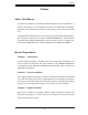
AS1021M-T2/1021M-82 User's Manual Figure 6-1. Chassis: Front and Rear Views Slim Floppy Drive Slim DVD-ROM Drive System LEDs (optional) SATA/SCSI Drive Bays Power Supply Module Mouse/Keyboard 6-2 USB Ports Control Panel System Reset Main Power PCI Expansion Slots (w/ riser cards) COM1 Port Ethernet Ports VGA Port Control Panel The control panel (located on the front of the chassis) must be connected to the JF1 connector on the serverboard to provide you with system status indications.
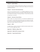
Chapter 6: Advanced Chassis Setup 6-3 System Fans Four 40-mm heavy duty counter-rotating fans provide the cooling for the AS1021MT2/1021M-82. Each fan unit is actually made up of two fans joined back-to-back, which rotate in opposite directions. This counter-rotating action generates exceptional airflow and works to dampen vibration levels.
AS1021M-T2/1021M-82 User's Manual Figure 6-2. System Cooling Fans 6-4 Drive Bay Installation/Removal Removing the Front Bezel If your system has a front bezel (optional) attached to the chassis, you must first remove it to gain access to the drive bays. To remove the bezel, first unlock the front of the chassis then press the release knob (see Figure 6-3). Carefully remove the bezel with both hands. A filter located within the bezel can be removed for replacement/cleaning.
Chapter 6: Advanced Chassis Setup Figure 6-3. Removing the Front Bezel 1. Unlock 2. Press release knob 3. Remove bezel assembly Accessing the Drive Bays SATA/SCSI Drives: Because of their hotswap capability, you do not need to access the inside of the chassis or power down the system to install or replace SATA or SCSI drives. Proceed to the next section for instructions.
AS1021M-T2/1021M-82 User's Manual SATA/SCSI Drive Installation 1. Mounting a SATA/SCSI drive in a drive carrier The SATA/SCSI drives are mounted in drive carriers to simplify their installation and removal from the chassis. These carriers also help promote proper airflow for the drive bays. For this reason, even empty carriers without drives installed must remain in the chassis.
Chapter 6: Advanced Chassis Setup 2. Installing/removing hot-swap SATA/SCSI drives The SATA/SCSI drive carriers are all easily accessible at the front of the chassis. These hard drives are hot-pluggable, meaning they can be removed and installed without powering down the system. To remove a carrier, push the release button located beside the drive LEDs. Then swing the colored handle fully out and use it to pull the unit straight out (see Figure 6-5).
AS1021M-T2/1021M-82 User's Manual DVD-ROM and Floppy Drive Installation The top cover of the chassis must be opened to gain full access to the DVD-ROM and floppy drive bays. The AS1021M-T2/1021M-82 accomodates only slim-line DVD-ROM drives. Side mounting brackets are needed to mount a slim-line DVDROM drive in the AS1021M-T2/1021M-82 server. You must power down the system before installing or removing a floppy or DVDROM drive. First, release the retention screws that secure the server unit to the rack.
Chapter 6: Advanced Chassis Setup 6-5 Power Supply The AS1021M-T2/1021M-82 has a single 560 watt power supply, which is autoswitching capable. This enables it to automatically sense and operate at a 100v to 240v input voltage. An amber light will be illuminated on the power supply when the power is off. An illuminated green light indicates that the power supply is operating. Power Supply Failure If the power supply unit fails, the system will shut down and you will need to replace the unit.
AS1021M-T2/1021M-82 User's Manual Figure 6-6.
Chapter 7: BIOS Chapter 7 BIOS 7-1 Introduction This chapter describes the AMIBIOS™ Setup utility for the H8DMR-82/H8DMR-i2. The AMI ROM BIOS is stored in a flash chip and can be easily upgraded using a floppy disk-based program. Note: Due to periodic changes to the BIOS, some settings may have been added or deleted and might not yet be recorded in this manual. Please refer to the Manual Download area of our web site for any changes to BIOS that may not be reflected in this manual.
AS1021M-T2/1021M-82 User's Manual 7-2 Main Menu When you first enter AMI BIOS Setup Utility, you will see the Main Menu screen. You can always return to the Main Menu by selecting the Main tab on the top of the screen with the arrow keys. The Main Menu screen provides you with a system overview, which includes the version, built date and ID of the AMIBIOS, the type, speed and number of the processors in the system and the amount of memory installed in the system.
Chapter 7: BIOS Advanced ACPI Configuration ACPI Version Features Use this setting the determine which ACPI version to use. Options are ACPI v1.0, ACPI v2.0 and ACPI v3.0. ACPI APIC Support Determines whether to include the ACPI APIC table pointer in the RSDT pointer list. The available options are Enabled and Disabled. ACPI OEMB Table Determines whether to include the ACPI APIC table pointer in the RSDT pointer list. The available options are Enabled and Disabled.
AS1021M-T2/1021M-82 User's Manual Floppy/IDE/SATA Configuration Onboard Floppy Controller Use this setting to Enable or Disable the onboard floppy controller. Floppy A Move the cursor to these fields via up and down keys to select the floppy type. The options are Disabled, 360 KB 5 1/4", 1.2 MB 5 1/4", 720 KB 3½", 1.44 MB 3½”, and 2.88 MB 3½". Onboard IDE Controller There is a single floppy controller on the motherboard, which may be Enabled or Disabled with this setting.
Chapter 7: BIOS Primary IDE Master/Slave Highlight one of the items above and press to access the submenu for that item. Type Select the type of device connected to the system. The options are Not Installed, Auto, CDROM and ARMD. LBA/Large Mode LBA (Logical Block Addressing) is a method of addressing data on a disk drive. The options are Disabled and Auto. Block (Multi-Sector Transfer) Block mode boosts IDE drive performance by increasing the amount of data transferred.
AS1021M-T2/1021M-82 User's Manual DMA Mode Selects the DAM Mode. Options are SWDMA0, SWDMA1, SWDMA2, MWDMA0. MDWDMA1, MWDMA2, UDMA0. UDMA1, UDMA2, UDMA3, UDMA4 and UDMA5. (SWDMA=Single Word DMA, MWDMA=Multi Word DMA, UDMA=UltraDMA.) S.M.A.R.T. Self-Monitoring Analysis and Reporting Technology (SMART) can help predict impending drive failures. Select "Auto" to allow BIOS to auto detect hard disk drive support. Select "Disabled" to prevent AMI BIOS from using the S.M.A.R.T.
Chapter 7: BIOS PIO Mode PIO (Programmable I/O) mode programs timing cycles between the IDE drive and the programmable IDE controller. As the PIO mode increases, the cycle time decreases. The options are Auto, 0, 1, 2, 3, and 4. Select Auto to allow AMI BIOS to auto detect the PIO mode. Use this value if the IDE disk drive support cannot be determined. Select 0 to allow AMI BIOS to use PIO mode 0. It has a data transfer rate of 3.3 MBs. Select 1 to allow AMI BIOS to use PIO mode 1.
AS1021M-T2/1021M-82 User's Manual PCI/PnP Configuration Load Onboard LAN Option ROM Use this setting to Enable or Disable the onboard option ROM. Clear NVRAM Select Yes to clear NVRAM during boot-up. The options are Yes and No. Plug & Play OS Select Yes to allow the OS to configure Plug & Play devices. (This is not required for system boot if your system has an OS that supports Plug & Play.) Select No to allow AMIBIOS to configure all devices in the system.
Chapter 7: BIOS Advanced Chipset Control NorthBridge Configuration Memory Configuration Memclock Mode This setting determines how the memory clock is set. Auto has the memory clock by code and Limit allows the user to set a standard value. MCT Timing Mode Sets the timing mode for memory. Options are Auto and Manual. Bank Interleaving Select Auto to automatically enable interleaving-memory scheme when this function is supported by the processor. The options are Auto and Disabled.
AS1021M-T2/1021M-82 User's Manual DRAM Scrub Redirect Allows system to correct DRAM ECC errors immediately, even with background scrubbing on. Options are Enabled and Disabled. DRAM BG Scrub Corrects memory errors so later reads are correct. Options are Disabled and various times in nanoseconds and microseconds. L2 Cache BG Scrub Allows L2 cache RAM to be corrected when idle. Options are Disabled and various times in nanoseconds and microseconds.
Chapter 7: BIOS MAC1 LAN1 Settings are Auto and Disabled for MAC1 LAN1. MAC1 LAN1 Bridge Settings are Enabled and Disabled for MAC1 LAN1 bridge. Legacy USB Support Select "Enabled" to enable the support for USB Legacy. Disable Legacy support if there are no USB devices installed in the system. "Auto" disabled Legacy support if no USB devices are connected. The options are Disabled, Enabled and Auto.
AS1021M-T2/1021M-82 User's Manual address and IRQ 3 for the interrupt address. The options are Disabled, 2F8/IRQ3, 3E8/IRQ4 and 2E8/IRQ3. Serial Port 2 Mode Tells BIOS which mode to select for serial port 2. The options are Normal, IrDA and ASKIR. DMI Event Logging View Event Log Highlight this item and press to view the contents of the event log. Mark All Events as Read Highlight this item and press to mark all events as read.
Chapter 7: BIOS Redirection After BIOS POST Options are Disable (no redirection after BIOS POST), Boot Loader (redirection during POST and during boot loader) and Always (redirection always active). Note that some OS's may not work with this set to Always. Terminal Type Selects the type of the target terminal. Options are ANSI, VT100 and VTUTF8. VT-UTF8 Combo Key Support Allows you to Enable or Disable VT-UTF8 combination key support for ANSI/ VT100 terminals.
AS1021M-T2/1021M-82 User's Manual FAN1 Speed through FAN5 Speed The speeds of the onboard fans (in rpm) are displayed here. FAN1 Speed Down Time Use the "+" and "-" keys to set the fan speed time interval of the ramp down. FAN1 Speed Up Time Use the "+" and "-" keys to set the fan speed time interval of the ramp up. Tolerance for Fan Control Set the fan control tolerance. Options are Disabled, 6ºC, 7ºC, 8ºC, 9ºC and 10ºC. Level1 Temperature Set the reference point to transfer to the next fan speed.
Chapter 7: BIOS IPMI 1.5 Configuration View BMC System Event Log Pressing the Enter key will open the following settings. Use the "+" and "-" keys to navigate through the system event log. Clear BMC System Event Log Selecting this and pressing the Enter key will clear the BMC system event log. Set LAN Configuration Use the "+" and "-" keys to choose the desired channel number. IP Address Use the "+" and "-" keys to select the parameter.
AS1021M-T2/1021M-82 User's Manual Startup Delay Use this setting to Enable or Disable the startup delay. Event Message for PEF Action Use this setting to Enable or Disable event messages for a PEF action. BMC Watch Dog Timer Action This setting is used to set the Watch Dog function. The options are Disabled, Reset System, Power Down and Power Cycle.
Chapter 7: BIOS CD/DVD Drives This feature allows the user to specify the Boot sequence from available CD/DVD drives. OS Installation Change this setting if using a 64-bit Linux operating system. The available options are Other and 64-bit Linux 2.6.9. 7-5 Security Menu AMI BIOS provides a Supervisor and a User password. If you use both passwords, the Supervisor password must be set first.
AS1021M-T2/1021M-82 User's Manual 7-6 Exit Menu Select the Exit tab from AMI BIOS Setup Utility screen to enter the Exit BIOS Setup screen. Save Changes and Exit When you have completed the system configuration changes, select this option to leave BIOS Setup and reboot the computer, so the new system configuration parameters can take effect. Select Save Changes and Exit from the Exit menu and press .
Appendix A: BIOS Error Beep Codes Appendix A BIOS Error Beep Codes During the POST (Power-On Self-Test) routines, which are performed each time the system is powered on, errors may occur. Non-fatal errors are those which, in most cases, allow the system to continue the boot-up process. The error messages normally appear on the screen. Fatal errors are those which will not allow the system to continue the boot-up procedure.
AS1021M-T2/1021M-82 User's Manual Notes A-2
Appendix B: BIOS POST Checkpoint Codes Appendix B BIOS POST Checkpoint Codes When AMIBIOS performs the Power On Self Test, it writes checkpoint codes to I/O port 0080h. If the computer cannot complete the boot process, diagnostic equipment can be attached to the computer to read I/O port 0080h. B-1 Uncompressed Initialization Codes The uncompressed initialization checkpoint codes are listed in order of execution: Checkpoint Code Description D0h The NMI is disabled. Power on delay is starting.
AS1021M-T2/1021M-82 User's Manual B-2 Bootblock Recovery Codes The bootblock recovery checkpoint codes are listed in order of execution: Checkpoint Code Description E0h The onboard floppy controller if available is initialized. Next, beginning the base 512 KB memory test. E1h Initializing the interrupt vector table next. E2h Initializing the DMA and Interrupt controllers next. E6h Enabling the floppy drive controller and Timer IRQs. Enabling internal cache memory.
Appendix B: BIOS POST Checkpoint Codes B-3 Uncompressed Initialization Codes The following runtime checkpoint codes are listed in order of execution. These codes are uncompressed in F0000h shadow RAM. Checkpoint Code Description 03h The NMI is disabled. Next, checking for a soft reset or a power on condition. 05h The BIOS stack has been built. Next, disabling cache memory. 06h Uncompressing the POST code next. 07h Next, initializing the CPU and the CPU data area.
AS1021M-T2/1021M-82 User's Manual Checkpoint Code Description 25h Interrupt vector initialization is done. Clearing the password if the POST DIAG switch is on. 27h Any initialization before setting video mode will be done next. 28h Initialization before setting the video mode is complete. Configuring the monochrome mode and color mode settings next. 2Ah Bus initialization system, static, output devices will be done next, if present. See the last page for additional information.
Appendix B: BIOS POST Checkpoint Codes Checkpoint Code Description 4Ch The memory below 1 MB has been cleared via a soft reset. Clearing the memory above 1 MB next. 4Dh The memory above 1 MB has been cleared via a soft reset. Saving the memory size next. Going to checkpoint 52h next. 4Eh The memory test started, but not as the result of a soft reset. Displaying the first 64 KB memory size next. 4Fh The memory size display has started. The display is updated during the memory test.
AS1021M-T2/1021M-82 User's Manual Checkpoint Code Description 86h The password was checked. Performing any required programming before WINBIOS Setup next. 87h The programming before WINBIOS Setup has completed. Uncompressing the WINBIOS Setup code and executing the AMIBIOS Setup or WINBIOS Setup utility next. 88h Returned from WINBIOS Setup and cleared the screen. Performing any necessary programming after WINBIOS Setup next. 89h The programming after WINBIOS Setup has completed.
Appendix B: BIOS POST Checkpoint Codes Checkpoint Code Description A9h Returned from adaptor ROM at E000h control. Performing any initialization required after the E000 option ROM had control next. Aah Initialization after E000 option ROM control has completed. Displaying the system configuration next. Abh Uncompressing the DMI data and executing DMI POST initialization next. B0h The system configuration is displayed. B1h Copying any code to specific areas.
AS1021M-T2/1021M-82 User's Manual Notes B-8
Appendix C: System Specifications Appendix C System Specifications Processors Single or dual AMD Socket F type processors Note: Please refer to our web site for a complete listing of supported processors. Chipset nVidia MCP55 Pro chipset BIOS 8 Mb Phoenix® Flash ROM Memory Capacity Eight 240-pin DIMM sockets supporting up to 16 GB of registered ECC DDR2667/533 or 32 GB of registered ECC DDR2-400 SDRAM Note: Memory may be installed to provide interleaved or non-interleaved confi gurations.
AS1021M-T2/1021M-82 User's Manual Motherboard 1021M-T2: H8DMR-i2 (Extended ATX form factor) 1021M-82: H8DMR-82 (Extended ATX form factor) Dimensions: 12 x 13.05 in (305 x 331 mm) Chassis 1021M-T2: SC815TQ+-560 Form Factor: 1U rackmount 1021M-82: SC815S+-560 Form Factor: 1U rackmount Dimensions: (WxHxD) 17 x 1.7 x 25.6 in. (432 x 43 x 650 mm) Weight Gross (Bare Bone): 40 lbs. (18.2 kg.
Appendix C: System Specifications Regulatory Compliance Electromagnetic Emissions: FCC Class A, EN 55022 Class A, EN 61000-3-2/-3-3, CISPR 22 Class A Electromagnetic Immunity: EN 55024/CISPR 24, (EN 61000-4-2, EN 61000-4-3, EN 61000-4-4, EN 61000-4-5, EN 61000-4-6, EN 61000-4-8, EN 61000-4-11) Safety: EN 60950/IEC 60950-Compliant, UL Listed (USA), CUL Listed (Canada), TUV Certified (Germany), CE Marking (Europe) C-3
AS1021M-T2/1021M-82 User's Manual Notes C-4