
User's Manual

Chapter 5: Advanced Motherboard Setup
5-11
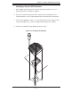
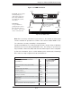
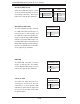
Figure 5-5. DIMM Installation
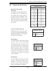
Note: Due to memory allocation to system devices, the amount of memory that
remains available for operational use will be reduced when 4 GB of RAM is used.
The reduction in memory availability is disproportional.
For Microsoft Windows users: Microsoft implemented a design change in Windows
XP with Service Pack 2 (SP2) and Windows Vista. This change is specifi c to the
Physical Address Extension (PAE) mode behavior which improves driver compatibil-
ity. For more information, please read the following article at Microsoft’s Knowledge
Base website at: http://support.microsoft.com/kb/888137.
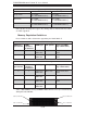
Possible System Memory Allocation & Availability
System Device Size
Physical Memory
Remaining (Available)
(4 GB Total System
Memory)
Firmware Hub fl ash memory (System BIOS) 1 MB 3.99
Local APIC 4 KB 3.99
Area Reserved for the chipset 2 MB 3.99
I/O APIC (4 Kbytes) 4 KB 3.99
PCI Enumeration Area 1 256 MB 3.76
PCI Express (256 MB) 256 MB 3.51
PCI Enumeration Area 2 (if needed) -Aligned on 256-
MB boundary-
512 MB 3.01
VGA Memory 16 MB 2.85
TSEG 1 MB 2.84
Memory available to OS and other applications 2.84
To Install: Insert module
vertically and press
down until it snaps into
place. Pay attention to
the alignment notch at
the bottom.
To Remove:
Use your thumbs to
gently push the release
tabs near both ends of
the module. This should
release it from the slot.
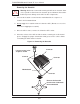
Top View of DDR3 Slot
Release Tab
Release Tab
Note: Notch should align
with the receptive key
point on the slot.
Notch
Notch
Front View