
User's Manual

5-16
SUPERSERVER 5016I-T/5016I-TF User's Manual
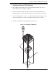
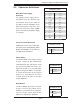
HDD LED
The HDD LED connection is located
on pins 13 and 14 of JF1. This LED is
used to display HDD activity. See the
table on the right for pin defi nitions.
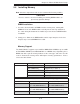
HDD LED
Pin Defi nitions (JF1)
Pin# Defi nition
13 +5V
14 HD Active
Power On LED
The Power On LED connector is lo-
cated on pins 15 and 16 of JF1 This
connection is used to provide LED
indication of power being supplied to
the system. See the table on the right
for pin defi nitions.
Power LED
Pin Defi nitions (JF1)
Pin# Defi nition
15 +5V
16 Control
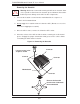
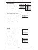
NIC1/NIC2 (LAN1/LAN2)
The NIC (Network Interface Control-
ler) LED connection for LAN port 1 is
located on pins 11 and 12 of JF1, and
the LED connection for LAN Port 2 is
on pins 9 and 10. NIC1 LED and NIC2
LED are 2-pin NIC LED headers. At-
tach NIC LED cables to NIC1 LED and
NIC2 LED to display network activities
for LAN 1 and LAN2. Refer to the table
on the right for pin defi nitions.
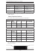
LAN1/LAN2 LED
Pin Defi nitions (JF1)
Pin# Defi nition
9/11 Vcc
10/12 Ground
Overheat (OH)/Fan Fail
Connect an LED cable to pins 7 and 8
of JF1 to provide warnings for chassis
overheating or fan failure. Refer to the
table on the right for pin defi nitions.
OH/Fan Fail LED
Pin Defi nitions (JF1)
Pin# Defi nition
7 Vcc/Blue UID LED
8 OH/Fan Fail LED
OH/Fan Fail Indicator
Status
State Defi nition
Off Normal
On Overheat
Flash-
ing
Fan Fail