
User's Manual

Chapter 5: Advanced Motherboard Setup
5-17
Fan Headers
The X8SIL/X8SIL-F has five fan
headers, all of which are 4-pin fans.
However, pins 1-3 of the fan headers
are backward compatible with the
traditional 3-pin fans. See the table
on the right for pin defi nitions. Fan 1
is intended for use with the CPU. A
fan speed control setting in the BIOS
Hardware Monitoring section allows
the BIOS to automatically set fan
speeds based on the system tempera-
ture. The default setting is Disabled
which allows the onboard fans to run
at full speed. Refer to the table on the
right for pin defi nitions.
ATX PS/2 Keyboard and PS/2
Mouse Ports
The ATX PS/2 keyboard and the PS/2
mouse are located on the I/O back-
panel. The mouse port is above the
keyboard port. See the table on the
right for pin defi nitions.
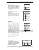
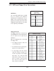
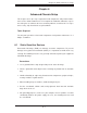
Fan Header
Pin Defi nitions
(FAN1-5)
Pin# Defi nition
1 Ground (Black)
2 2.5A/+16V (Red)
3 Tachometer
4 PWM Control
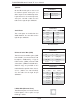
PS/2 Keyboard and
Mouse Port Pin
Defi nitions
Pin# Defi nition
1 Data
2NC
3 Ground
4 VCC
5 Clock
6NC
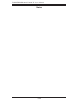
Chassis Intrusion
The Chassis Intrusion header is des-
ignated JL1. Attach an appropriate
cable from the chassis to inform you
of a chassis intrusion when the chas-
sis is opened
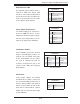
Chassis Intrusion
Pin Defi nitions (JL1)
Pin# Defi nition
1 Intrusion Input
2 Ground
Note: Please use all 3-pin fans or all 4-pin fans
on a motherboard. Please do not use 3-pin fans
and 4-pin fans on the same board.
Onboard Speaker
The onboard speaker (SPKR1) can be
used to provide audible indications for
various beep codes. See the table on
the right for pin defi nitions.
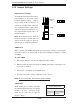
Onboard Speaker
Pin Defi nition
Pin# Defi nitions
Pin 1 Pos. (+) Beep In
Pin 2 Neg. (-) Alarm
Speaker