
User's Manual

Chapter 5: Advanced Motherboard Setup
5-15
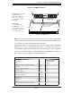
5-9 Connector Defi nitions
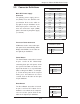
ATX Power 24-pin Connector
Pin Defi nitions (JPW1)
Pin# Defi nition Pin # Defi nition
13 +3.3V 1 +3.3V
14 -12V 2 +3.3V
15 COM 3 COM
16 PS_ON 4 +5V
17 COM 5 COM
18 COM 6 +5V
19 COM 7 COM
20 Res (NC) 8 PWR_OK
21 +5V 9 5VSB
22 +5V 10 +12V
23 +5V 11 +12V
24 COM 12 +3.3V
Power Button
Pin Defi nitions (JF1)
Pin# Defi nition
1 PW_ON
2 Ground
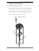
Main ATX Power Supply
Connector
The primary power supply connec-
tor (JPW1) meets the SSI EPS 12V
specifi cation. Refer to the table on
the right for the pin defi nitions of the
ATX 24-pin power connector. You
must also connect the 8-pin (JPW2)
power connector to your power supply
(see below).
Required Connection
Required Connection
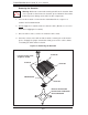
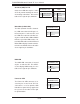
8-pin (+12V) Processor Power
Pin Defi nitions (JPW2)
Pins Defi nition
1 - 4 Ground
5 - 8 +12V
Processor Power Connector
JPW2 must also be connected to pro-
vide power to the South Bridge, North
Bridge and all VRMs. See the table on
the right for pin defi nitions.
Power Button
The Power Button connection is located
on pins 1 and 2 of JF1. Momentarily
contacting both pins will power on/off
the system. This button can also be con-
fi gured to function as a suspend button
(with a setting in the BIOS - see Chapter
7). To turn off the power in the suspend
mode, press the button for at least 4
seconds. Refer to the table on the right
for pin defi nitions.
Reset Button
The Reset Button connection is located
on pins 3 and 4 of JF1. Attach it to a
hardware reset switch on the computer
case to reset the system. Refer to the
table on the right for pin defi nitions.
Reset Button
Pin Defi nitions (JF1)
Pin# Defi nition
3 Reset
4 Ground