
User's Manual

Chapter 5: Advanced Serverboard Setup
5-17
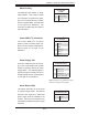
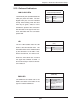
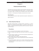
Wake-On-Ring
The Wake-On-Ring header is desig-
nated JWOR. This function allows
your computer to receive and "wake-
up" by an incoming call to the modem
when in suspend state. See the table
on the right for pin defi nitions. You
must have a WOR card and cable to
use this feature.
Wake-On-Ring
Pin Defi nitions
(JWOR)
Pin# Defi nition
1 Ground (Black)
2 Wake-up
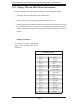
Power SMB (I
2
C) Connector
The Power SMB (I
2
C) connector
(PW4) is used to monitor power sup-
plies, fans and system temperatures.
See the table on the right for pin
defi nitions.
PWR SMB (I
2
C)
Pin Defi nitions
Pin# Defi nition
1 Clock
2 Data
3 PWR Fail
4 Ground
5 +3.3V
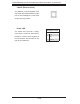
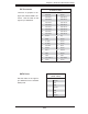
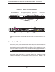
Power Supply Fail
Connect a cable from your power sup-
ply to the Power Supply Fail header
(PW3) to provide a warning of power
supply failure. This warning signal is
passed through the PWR_LED pin to
indicate a power failure. See the table
on the right for pin defi nitions.
Note: This feature is only available when using
Supermicro redundant power supplies.
Power Supply Fail
Pin Defi nitions (PW3)
Pin# Defi nition
1 PWR 1: Fail
2 PWR 2: Fail
3 PWR 3: Fail
4 Signal: Alarm Reset
Alarm Reset (JAR)
The system will notify you in the event
of a power supply failure. This feature
assumes that Supermicro redundant
power supply units are installed in the
chassis. Connect a microswitch to the
JAR header to disable the power supply
fail alarm.
Alarm Reset
Pin Defi nitions (JAR)
Pin# Defi nition
1 Ground
2 +5V