
Owner manual


Chapter 5: Advanced Motherboard Setup
5-13
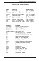
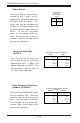
Overheat LED (OH)
Connect an LED to the OH connec-
tion on pins 7 and 8 of JF2 to pro-
vide advanced warning of chassis
overheating. Refer to the table on
the right for pin definitions.
Reset Button
The Reset Button connection is lo-
cated on pins 3 and 4 of JF2. At-
tach it to the hardware reset
switch on the computer case.
Refer to the table on the right for
pin definitions.
Pin
Number
3
4
Definition
Reset
Ground
Reset Pin
Definitions
(JF2)
NIC1 LED
The NIC1 (Network Interface Con-
troller) LED connection is located
on pins 11 and 12 of JF2. Attach
the NIC1 LED cable to display net-
work activity. Refer to the table
on the right for pin definitions.
NIC1 LED Pin
Definitions
(JF2)
Pin
Number
11
12
Definition
Vcc
GND
Overheat (OH) LED
Pin Definitions
(JF2)
Pin
Number
7
8
Definition
Vcc
GND
Power Fail LED
The Power Fail LED connection is
located on pins 5 and 6 of JF2.
Refer to the table on the right for
pin definitions. This only applies
to redundant power supplies and
so does not apply to the 6012P-6.
Power Fail Button
Pin Definitions
(JF2)
Pin
Number
5
6
Definition
Vcc
GND
NIC2 LED
The NIC2 (Network Interface Con-
troller) LED connection is located
on pins 9 and 10 of JF2. Attach
the NIC2 LED cable to display net-
work activity. Refer to the table
on the right for pin definitions.
NIC2 LED Pin
Definitions
(JF2)
Pin
Number
9
10
Definition
Vcc
GND