SUPER ® SUPERSERVER 6014L-T USER’S MANUAL Revision 1.
The information in this User’s Manual has been carefully reviewed and is believed to be accurate. The vendor assumes no responsibility for any inaccuracies that may be contained in this document, makes no commitment to update or to keep current the information in this manual, or to notify any person or organization of the updates. Please Note: For the most up-to-date version of this manual, please see our web site at www.supermicro.com.
Preface Preface About This Manual This manual is written for professional system integrators and PC technicians. It provides information for the installation and use of the SuperServer 6014L-T. Installation and maintenance should be performed by experienced technicians only. The SuperServer 6014L-T is a high-end dual processor rackmount server based on the SC811LT-260 1U rackmount server chassis and the Super X6DLP-EG2 serverboard.
SUPERSERVER 6014L-T User's Manual Chapter 4: System Safety You should thoroughly familiarize yourself with this chapter for a general overview of safety precautions that should be followed when installing and servicing the SuperServer 6014L-T. Chapter 5: Advanced Serverboard Setup Chapter 5 provides detailed information on the X6DLP-EG2 serverboard, including the locations and functions of connectors, headers and jumpers.
Preface Notes v
SUPERSERVER 6014L-T User's Manual Table of Contents Preface About This Manual ...................................................................................................... iii Manual Organization ................................................................................................... iii Chapter 1: Introduction 1-1 Overview ......................................................................................................... 1-1 1-2 Serverboard Features ..........................
Table of Contents Power ....................................................................................................... 3-3 3-4 Serial ATA Drive Carrier LEDs ......................................................................... 3-3 Chapter 4: System Safety 4-1 Electrical Safety Precautions .......................................................................... 4-1 4-2 General Safety Precautions ...........................................................................
SUPERSERVER 6014L-T User's Manual Speaker/Power LED/Keylock ................................................................. 5-16 Wake-On-Ring ........................................................................................ 5-16 Wake-On-LAN ........................................................................................ 5-16 Power Fault ............................................................................................ 5-17 ATX PS/2 Keyboard and PS/2 Mouse Ports ...................
Table of Contents Chapter 7: BIOS 7-1 Introduction ..................................................................................................... 7-1 7-2 Main Setup ..................................................................................................... 7-2 7-3 Advanced Settings .......................................................................................... 7-3 7-4 Boot Settings ...........................................................................................
SUPERSERVER 6014L-T User's Manual Notes x
Chapter 1: Introduction Chapter 1 Introduction 1-1 Overview The SuperServer 6014L-T is a high-end dual processor, 1U rackmount server featuring state-of-the-art technology. The 6014L-T is comprised of two main subsystems: the SC811LT-260 1U rackmount chassis and the X6DLP-EG2 serverboard. Please refer to our web site for information on operating systems that have been certified for use with the 6014L-T (www.supermicro.com).
SUPERSERVER 6014L-T User's Manual 1-2 Serverboard Features At the heart of the SuperServer lies the X6DLP-EG2, a dual processor serverboard based on Intel's E7520 chipset and designed to provide maximum performance. Below are the main features of the X6DLP-EG2. Processors The X6DLP-EG2 supports single or dual Intel® Xeon® LV or ULV processors in 479-pin PGA sockets. Please refer to our web site for a complete listing of supported processors (www.supermicro.com).
Chapter 1: Introduction Onboard Controllers/Ports An onboard IDE controller supports up to four UltraDMA/100 hard drives or ATAPI devices. Onboard I/O backpanel ports include one COM port, a VGA port, two USB ports, PS/2 mouse and keyboard ports and two GLAN (NIC) ports. Other Features Other onboard features that promote system health include voltage monitors, a chassis intrusion header, auto-switching voltage regulators, chassis and CPU overheat sensors, virus protection and BIOS rescue.
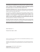
SUPERSERVER 6014L-T User's Manual CPU1 CPU2 667 MT/s DDR2-400 Group A DIMM 1A Links0-7 8x PCI-Express (Slot 6) DIMM 2A DIMM 3A 8x PCI-Express (Slot 3) Group B Links0-7 LAN 82573 LAN 82573 E7520 MCH DIMM 4A DIMM 1B DIMM 2B DIMM 3B DIMM 4B PCI-X 66 MHz (Slot 6) SATA Ports (4) PCI-X 66 MHz (Slot 5) 6300ESB IDE (ATA133) PCI 33 MHz (Slot 1) USB Ports (4) ATI Rage LPC BIOS Kybd/ Mouse S I/O Floppy IPMI COM Ports Figure 1-1 .
Chapter 1: Introduction 1-3 Server Chassis Features The following is a general outline of the main features of the SC811LT-260 chassis. System Power When configured as a SuperServer 6014L-T, the SC811LT-260 chassis includes a single 260W power supply. Serial ATA Subsystem For the 6014L-T, the SC811LT-260 chassis was designed to support two Serial ATA hard drives, which are hot-swappable units.
SUPERSERVER 6014L-T User's Manual Figure 1-2. Rear I/O Panel Cooling System The SC811LT-260 chassis has an innovative cooling design that features three 4-cm high-performance system cooling fans. Each of these fans plug into a chassis fan header on the serverboard. An air shroud channels the airflow generated by the fans to efficiently cool the processor area of the system.
Chapter 1: Introduction 1-4 Contacting Supermicro Headquarters Address: Tel: Fax: Email: Web Site: SuperMicro Computer, Inc. 980 Rock Ave. San Jose, CA 95131 U.S.A. +1 (408) 503-8000 +1 (408) 503-8008 marketing@supermicro.com (General Information) support@supermicro.com (Technical Support) www.supermicro.com Europe Address: Tel: Fax: Email: SuperMicro Computer B.V. Het Sterrenbeeld 28, 5215 ML 's-Hertogenbosch, The Netherlands +31 (0) 73-6400390 +31 (0) 73-6416525 sales@supermicro.
SUPERSERVER 6014L-T User's Manual Notes 1-8
Chapter 2: Server Installation Chapter 2 Server Installation 2-1 Overview This chapter provides a quick setup checklist to get your SuperServer 6014L-T up and running. Following the steps in the order given should enable you to have the system operational within a minimal amount of time. This quick setup assumes that your 6014L-T system has come to you with the processor and memory preinstalled. If your system is not already fully integrated with a serverboard, processor, system memory etc.
SUPERSERVER 6014L-T User's Manual Choosing a Setup Location - Leave enough clearance in front of the rack to enable you to open the front door completely (~25 inches). - Leave approximately 30 inches of clearance in the back of the rack to allow for sufficient airflow and ease in servicing. - This product is for installation only in a Restricted Access Location (dedicated equipment rooms, service closets and the like).
Chapter 2: Server Installation Rack Mounting Considerations Ambient Operating Temperature If installed in a closed or multi-unit rack assembly, the ambient operating temperature of the rack environment may be greater than the ambient temperature of the room. Therefore, consideration should be given to installing the equipment in an environment compatible with the manufacturer’s maximum rated ambient temperature (Tmra).
SUPERSERVER 6014L-T User's Manual 2-4 Installing the System into a Rack This section provides information on installing the SuperServer 6014L-T into a rack unit. If the system has already been mounted into a rack, you can skip ahead to Sections 2-5 and 2-6. There are a variety of rack units on the market, which may mean the assembly procedure will differ slightly. The following is a guideline for installing the unit into a rack with the rack rails provided with the system.
Chapter 2: Server Installation Installing the Chassis Rails Position the fixed chassis rail sections you just removed along the side of the chassis making sure the five screw holes line up. Note that these two rails are left/right specific. Screw the rail securely to the side of the chassis (see Figure 2-2). Repeat this procedure for the other rail on the other side of the chassis. You will also need to attach the rail brackets when installing into a telco rack.
SUPERSERVER 6014L-T User's Manual Installing the Server into the Rack You should now have rails attached to both the chassis and the rack unit. The next step is to install the server into the rack. Do this by lining up the rear of the chassis rails with the front of the rack rails. Slide the chassis rails into the rack rails, keeping the pressure even on both sides (you may have to depress the locking tabs when inserting). See Figure 2-3.
Chapter 2: Server Installation Installing the Server into a Telco Rack If you are installing the SuperServer 6014L-T into a Telco type rack, follow the directions given on the previous pages for rack installation. The only difference in the installation procedure will be the positioning of the rack brackets to the rack. They should be spaced apart just enough to accomodate the width of the telco rack. Figure 2-4.
SUPERSERVER 6014L-T User's Manual 2-5 Checking the Serverboard Setup After you install the 6014L-T in the rack, you will need to open the unit to make sure the serverboard is properly installed and all the connections have been made. 1. Accessing the inside of the system (Figure 2-5) First, grasp the two handles on either side and pull the unit straight out until it locks (you will hear a "click"). Next, depress the two buttons on the top of the chassis to release the top cover.
Chapter 2: Server Installation Figure 2-5.
SUPERSERVER 6014L-T User's Manual 2-6 Checking the Drive Bay Setup Next, you should check to make sure the peripheral drives and the Serial ATA drives and Serial ATA backplane have been properly installed and all essential connections have been made. 1. Accessing the drive bays All drives can be accessed from the front of the server. For servicing the CDROM and floppy drives, you will need to remove the top chassis cover.
Chapter 3: System Interface Chapter 3 System Interface 3-1 Overview There are several LEDs on the control panel as well as others on the Serial ATA drive carriers to keep you constantly informed of the overall status of the system as well as the activity and health of specific components. There are also two buttons on the chassis control panel. This chapter explains the meanings of all LED indicators and the appropriate response you may need to take.
SUPERSERVER 6014L-T User's Manual 3-3 Control Panel LEDs The control panel located on the front of the chassis has five LEDs. These LEDs provide you with critical information related to different parts of the system. This section explains what each LED indicates when illuminated and any corrective action you may need to take. Overheat/Fan Fail: When this LED flashes, it indicates a fan failure.
Chapter 3: System Interface Power: Indicates power is being supplied to the system's power supply units. This LED should normally be illuminated when the system is operating. 3-4 Serial ATA Drive Carrier LED Each Serial ATA drive carrier has a green LED. When illuminated, this green LED (on the front of the Serial ATA drive carrier) indicates drive activity. A connection to the Serial ATA backplane enables this LED to blink on and off when that particular drive is being accessed.
SUPERSERVER 6014L-T User's Manual Notes 3-4
Chapter 4: System Safety Chapter 4 System Safety 4-1 Electrical Safety Precautions ! Basic electrical safety precautions should be followed to protect yourself from harm and the SuperServer 6014L-T from damage: Be aware of the locations of the power on/off switch on the chassis as well as the room's emergency power-off switch, disconnection switch or electrical outlet. If an electrical accident occurs, you can then quickly remove power from the system.
SUPERSERVER 6014L-T User's Manual Serverboard Battery: CAUTION - There is a danger of explosion if the onboard battery is installed upside down, which will reverse its polarites (see Figure 4-1). This battery must be replaced only with the same or an equivalent type recommended by the manufacturer. Dispose of used batteries according to the manufacturer's instructions. CD-ROM Laser: CAUTION - this server may have come equipped with a CDROM drive.
Chapter 4: System Safety 4-3 ESD Precautions ! Electrostatic discharge (ESD) is generated by two objects with different electrical charges coming into contact with each other. An electrical discharge is created to neutralize this difference, which can damage electronic components and printed circuit boards.
SUPERSERVER 6014L-T User's Manual 4-4 Operating Precautions ! Care must be taken to assure that the chassis cover is in place when the 6014L-T is operating to assure proper cooling. Out of warranty damage to the 6014L-T system can occur if this practice is not strictly followed. Figure 4-1.
Chapter 5: Advanced Serverboard Setup Chapter 5 Advanced Serverboard Setup This chapter covers the steps required to install processors, memory and heatsinks to the X6DLP-EG2 serverboard, connect the data and power cables and install add-on cards. All serverboard jumpers and connections are described and a layout and quick reference chart are included in this chapter. Remember to close the chassis completely when you have finished working on the serverboard to protect and cool the system.
SUPERSERVER 6014L-T User's Manual 5-2 Serverboard Installation This section explains how to mount the X6DLP-EG2 into the SC811LT-260 chassis. Following the steps in the order given will eliminate the most common problems encountered in such an installation. To access the inside of the server, remove the screws from the back lip of the top cover of the chassis, then pull the cover off. Note: Before you install the serverboard you should first attach the heatsink brackets to the back of the serverboard.
Chapter 5: Advanced Serverboard Setup 5-3 Processor and Heatsink Installation Avoid placing direct pressure to the top of the processor package. Also, never place the serverboard on a conductive ! surface. Always remove the power cord first before adding, removing or changing any hardware components. The X6DLP-EG2 has two 479-pin PGA sockets that support Intel® Xeon® LV or ULV processors. Important: Make sure that you have installed the heatsink bracket(s) to the back of the serverboard first.
SUPERSERVER 6014L-T User's Manual 5. Once the processor is properly seated in the socket, turn the lock mechanism clockwise with the flathead screw driver to lock it. Repeat the above steps if you wish to install a secind processor. Installing the Heatsinks Installed processor 1. Do not apply any thermal grease to the heatsink or the CPU die; the if the required amount has already been applied . 2. Locate the four heatsink mounting holes on the serverboard. Heatsink mounting holes Screw# 1 3.
Chapter 5: Advanced Serverboard Setup Removing the Heatsink 1. Using a Phillips screwdriver to remove the Screw# 1 heatsink screws from the serverboard (remove diagonal screws first, as show in the picture on the right). Screw# 2 2. Hold the heatsink and gently wriggle the heatsink to loosen it from the processor. (Do not use excessive force when wriggling the heatsink!!) 3. Once the heatsink has been loosened, remove the heatsink from the processor. 4.
SUPERSERVER 6014L-T User's Manual 5-4 Connecting Cables Now that the processors are installed, the next step is to connect the cables to the serverboard. These include the data (ribbon) cables for the peripherals and control panel and the power cables. Connecting Data Cables The ribbon cables used to transfer data from the peripheral devices have been carefully routed in preconfigured systems to prevent them from blocking the flow of cooling air that moves through the system from front to back.
Chapter 5: Advanced Serverboard Setup Connecting the Control Panel JF1 contains header pins for various front control panel connectors. See Figure 5-1 for the pin locations of the various front control panel buttons and LED indicators. Note that even and odd numbered pins are on opposite sides of each header. All JF1 wires have been bundled into single ribbon cable to simplify their connection. Make sure the red wire plugs into pin 1 as marked on the board.
SUPERSERVER 6014L-T User's Manual 5-6 Installing Memory Note: Check the Supermicro web site for recommended memory modules: http:// www.supermicro.com/support/resources/ CAUTION Exercise extreme care when installing or removing DIMM modules to prevent any possible damage. DIMM Installation (See Figure 5-3) 1. Insert the desired number of DIMMs into the memory slots, starting with DIMM1A and DIMM1B. Pay attention to the notch along the bottom of the module to prevent inserting the module incorrectly.
Chapter 5: Advanced Serverboard Setup 5-7 Adding PCI Cards 1. PCI slots The 6014L-T system includes a CSE-RR1U-X riser card. This riser fits into a 66 MHz PCI slot to support a full-height, half-length PCI add-on card. There is also the option of using the (optional) CSE-RR1U-EL riser card to support the use of an expansion card in the x8 PCI-Express slot. 2. PCI card installation Before installing a PCI add-on card, see step 1, above.
SUPERSERVER 6014L-T User's Manual 5-8 Serverboard Details Figure 5-4.
Chapter 5: Advanced Serverboard Setup X6DLP-EG2 Quick Reference Jumper Description Default Setting J13/J15 PCI/PCI-X Slots to System SMB Open (Disabled) JBT1 CMOS Clear See Section 5-9 JPF JPG1 Power Force On VGA Enable Open (Disabled) Pins 1-2 (Enabled) JPL1/JPL2 JLAN1/JLAN 2 Enable/Disable Pins 1-2 (Enabled) JPR1 Power Fail Alarm Reset Open (Disabled) JWD Watch Dog Enable Pins 1-2 (Enabled) Connector Description COM1/COM2 FAN 1-6 Floppy IDE1/IDE2 IPMI I-SATA0/1 JF1 JF2 JL1 JLAN 1/2
SUPERSERVER 6014L-T User's Manual 5-9 Connector Definitions ATX Power 24-pin Connector Pin Definitions (PW1) ATX Power Connector The main power supply connector on the X6DPL-EG2 meets the SSI EPS 12V specification. See the table on the right for pin definitions. Note: You must also connect the processor power connector (PW2, below.) Pin# Definition Pin # Definition 13 +3.3V 1 +3.3V 14 -12V 2 +3.
Chapter 5: Advanced Serverboard Setup HDD LED HDD LED Pin Definitions (JF1) The HDD LED (for IDE and SATA Pin# Definition drives) connection is located on pins 13 Vcc 13 and 14 of JF1. Attach the drive LED cable to these pins to display disk 14 HD Active activity. See the table on the right for pin definitions.
SUPERSERVER 6014L-T User's Manual Reset Button The Reset Button connection is lo- Reset Button Pin Definitions (JF1) cated on pins 3 and 4 of JF1. Attach Pin# Definition it to the hardware reset switch on the computer case. Refer to the table on 3 Reset 4 Ground the right for pin definitions. Power Button Power Button Pin Definitions (JF1) The Power Button connection is located on pins 1 and 2 of JF1. Momentarily contacting both pins will power on/off the system.
Chapter 5: Advanced Serverboard Setup Universal Serial Bus (USB0/1) Universal Serial Bus Pin Definitions (USB0/1) Two USB 2.0 ports are located beside the LAN ports. USB0 is the bottom port and USB1 is the top port. See the table on the right for pin definitions.
SUPERSERVER 6014L-T User's Manual Speaker/Power LED/Keylock Speaker Connection Pin Definitions On the JF2 header, pins 1, 3, 5 and 1 Red Wire, Speaker Data 7 are for the speaker, pins 2, 4 and 6 3 No Connection are for the power LED and pins 8 and 10 are for the keylock. Pin 9 is absent 5 Key 7 Speaker Data (key). See the table on the right for PWR LED/Keylock Connection Pin Definitions speaker pin definitions. Note: The speaker connector pins are for use with an external speaker.
Chapter 5: Advanced Serverboard Setup Power Fault PWR Fault Connection Pin Definitions (PW4) Connect a cable from your power supply to the PW4 header to provide Pin# Definition warning of power supply failure. This warning signal is passed through the 1 PWR 1 Fail Signal 2 PWR 2 Fail Signal PWR_LED pin to indicate of a power 3 PWR 3 Fail Signal failure on the chassis. See the table 4 PWR 4 Fail Signal on the right for pin definitions.
SUPERSERVER 6014L-T User's Manual 5-10 Jumper Settings Explanation of Jumpers To modify the operation of the 3 2 1 3 2 1 Connector Pins serverboard, jumpers can be used to choose between optional settings. Jumpers create shorts between two Jumper pins to change the function of the connector. Pin 1 is identified with a Setting square solder pad on the printed circuit board. See the serverboard layout pages for jumper locations.
Chapter 5: Advanced Serverboard Setup VGA Enable/Disable VGA Enable/Disable Jumper Settings (JPG1) Jumper Setting JPG1 enables or disables the VGA Definition port on the serverboard. See the table Pins 1-2 Enabled on the right for jumper settings. Pins 2-3 Disabled SMBus to PCI Slots SMBus to PCI Jumper Settings (J13, J15) Jumpers J13 and J15 allow you to connect the PCI-X/PCI slots to the System Jumper Setting Management Bus. The default setting is open to disable the connection.
SUPERSERVER 6014L-T User's Manual Alarm Reset The system will notify you in the event of Alarm Reset Jumper Settings a power supply failure. This feature assumes that Supermicro redundant power supply units are installed in the chassis. Jumper Setting Open Enabled If you only have a single power supply Closed Disabled Definition installed, you should not connect anything to this header (JPR1) to prevent false alarms. See the table on the right for jumper settings.
Chapter 5: Advanced Serverboard Setup Onboard LED Indicators (DS1, DS5) LED Indicators (DS1, DS5) DS1 and DS5 are additional LED DS# Definition (when illuminated) DS1 CPU PWR bad or processor power cable not connected DS5 Power present on serverboard indicators on the X6DLP-EG2. See the table on the right for information regarding these two LEDs. Onboard LED Indicators (DS7, DS8) DS7 and DS8 are POST code LEDs. Please refer to Appendix A for POST code information.
SUPERSERVER 6014L-T User's Manual 5-12 Parallel Port, Floppy, IDE and SATA Drive Connections Note the following when connecting the floppy and hard disk drive cables: • The floppy disk drive cable has seven twisted wires. • A red mark on a wire typically designates the location of pin 1. • A single floppy disk drive ribbon cable has 34 wires and two connectors to provide for two floppy disk drives.
Chapter 5: Advanced Serverboard Setup Floppy Connector Floppy Drive Connector Pin Definitions (Floppy) The floppy connector is des- Pin# Definition ignated "Floppy". See the 1 Ground 2 FDHDIN table to the right for pin definitions.
SUPERSERVER 6014L-T User's Manual IDE Connectors There are no jumpers to configure the onboard IDE connectors. See the table below for pin definitions.
Chapter 6: Advanced Chassis Setup Chapter 6 Advanced Chassis Setup This chapter covers the steps required to install components and perform maintenance on the SC811LT-260 chassis. For component installation, follow the steps in the order given to eliminate the most common problems encountered. If a step is unnecessary, skip ahead to the step that follows. Tools Required The only tool you will need to install components and perform maintainance is a Philips screwdriver.
SUPERSERVER 6014L-T User's Manual Figure 6-1. Chassis Front View Figure 6-2. Chassis Rear View 6-2 Control Panel The control panel (located on the front of the chassis) must be connected to the JF1 connector on the serverboard to provide you with system control buttons and status indicators. These wires have been bundled together in a ribbon cable to simplify the connection. Connect the cable from JF1 on the serverboard to the correct neader on the Control Panel PCB (printed circuit board).
Chapter 6: Advanced Chassis Setup 6-3 System Fans Two 4-cm fans provide the cooling for the SuperServer 6014L-T. Air seals are used at the chassis cross section, which separates the drive bay area from the serverboard area of the chassis to promote better airflow. It is highly important that the air seal is properly installed and making a good seal in order for the cooling air to circulate properly through the chassis.
SUPERSERVER 6014L-T User's Manual Serial ATA Drive Installation 1. Mounting a Serial ATA drive in a drive carrier The Serial ATA drives are mounted in drive carriers to simplify their installation and removal from the chassis. These carriers also help promote proper airflow for the Serial ATA drive bays. For this reason, even empty carriers without Serial ATA drives installed must remain in the chassis.
Chapter 6: Advanced Chassis Setup 2. Installing/removing hot-swap Serial ATA drives Two Serial ATA drive bays are located in the front of the chassis, making them easily accessible for installation and removal. These drives are hot-swappable, meaning they can be installed and removed without powering down the system. To remove, first push the release button located beside the drive LEDs, then swing the colored handle fully out and use it to pull the unit straight out (see Figure 6-4). Figure 6-4.
SUPERSERVER 6014L-T User's Manual Serial ATA Backplane The Serial ATA drives plug into a backplane that provides power, drive ID and bus termination. A RAID controller can be used with the backplane to provide data security. The operating system you use must have RAID support to enable the hot-swap capability of the Serial ATA drives. The backplane has two jumpers as follows: JP18: Alarm reset JP25: Hard drive temperature threshold Settings: Open = 45º, Pins 1-2 = 50º, Pins 2-3 = 55º.
Chapter 6: Advanced Chassis Setup 6-5 Power Supply The SuperServer 6014L-T has a single 260 watt power supply. This power supply has the capability of operating at 100 or 240 input volts. Depress the main power button on the front of the chassis and then unplug the AC power cord to completely remove power from the system before removing the power supply. Power Supply Failure If the power supply unit fails, the system will shut down and you will need to replace the power supply unit.
SUPERSERVER 6014L-T User's Manual Notes 6-8
Chapter 7: BIOS Chapter 7 BIOS 7-1 Introduction This chapter describes the AMIBIOS Setup Utility for the X6DLP-EG2. The AMI ROM BIOS is stored in a Flash EEPROM and can be easily upgraded using a floppy disk-based program. This chapter describes the basic navigation of the AMIBIOS Setup Utility setup screens. Starting the BIOS Setup Utility To enter the AMIBIOS Setup Utility screens, hit the key while the system is booting up. Each main BIOS menu option is described in this user’s guide.
SUPERSERVER 6014L-T User's Manual 7-2 Main Setup When you first enter the AMI BIOS Setup Utility, you will enter the Main setup screen. You can always return to the Main setup screen by selecting the Main tab on the top of the screen. The Main BIOS Setup screen is shown below.
Chapter 7: BIOS System Time/System Date Use this option to change the system time and date. Highlight System Time or System Date using the arrow keys. Enter new values through the keyboard. Press the key or the arrow keys to move between fields. The date must be entered in DAY/MM/DD/YY format. The time is entered in HH:MM:SS format.(*Note: The time is in 24-hour format. For example, 5:30 A.M. appears as 05:30:00, and 5:30P. M. as 17:30:00.
SUPERSERVER 6014L-T User's Manual Execute Disable Bit (Available when supported by the OS and the CPU.) Set to Enabled to enable the Execute Disable Bit to allow the processor to classify areas in the system memory where an application code can and cannot execute, thus preventing a worm or a virus from creating a flood of codes to overwhelm the processor or damage the system during an attack.
Chapter 7: BIOS Type Select the type of device connected to the system. The options are Not Installed, Auto, CDROM and ARMD. LBA/Large Mode LBA (Logical Block Addressing) is a method of addressing data on a disk drive. In the LBA mode, the maximum drive capacity is 137 GB. For drive capacities over 137 GB, your system must be equipped with a 48-bit LBA mode addressing. If not, contact your manufacturer or install an ATA/133 IDE controller card that supports 48-bit LBA mode.
SUPERSERVER 6014L-T User's Manual 32Bit Data Transfer Select "Enabled" to activate the 32-bit data transfer function. Select "Disabled" to disable this function. The options are Enabled and Disabled. Hard Disk Write Protect Select Enabled to enable the function of Hard Disk Write Protect to prevent data from being written to HDD. The options are Enabled or Disabled. IDE Detect Time Out This feature allows the user to set the time-out value for detecting ATA and ATAPI devices installed in the system.
Chapter 7: BIOS 96 PCI clock cycles. Select "128" to set the PCI latency to 128 PCI clock cycles. Select "160" to set the PCI latency to 160 PCI clock cycles. Select "192" to set the PCI latency to 192 PCI clock cycles. Select "224" to set the PCI latency to 224 PCI clock cycles. Select "248" to set the PCI latency to 248 PCI clock cycles. Allocate IRQ to PCI VGA Set this value to allow or restrict the system from giving the VGA adapter card an interrupt address. The options are Yes and No.
SUPERSERVER 6014L-T User's Manual Super IO Configuration Sub-Menu Serial Port1 Address This option specifies the base I/O port address and the Interrupt Request address of Serial Port 1. Select "Disabled" to prevent the serial port from accessing any system resources. When this option is set to Disabled, the serial port physically becomes unavailable. Select "3F8/IRQ4" to allow the serial port to use 3F8 as its I/O port address and IRQ 4 for the interrupt address.
Chapter 7: BIOS Advanced Chipset Settings This item allows the user to configure the Advanced Chipset settings for the system. NorthBridge Configuration This feature allows the user to configure the settings for the Intel E7520 NorthBridge chipset. Memory Remap Feature Select Enabled to allow remapping of the overlapped PCI memory above the total physical memory. The options are Enabled and Disabled.
SUPERSERVER 6014L-T User's Manual APCI Configuration This item allows the user to enable or disable the ACPI support for the operating system. ACPI Configuration Use this feature to configure additional ACPI options. Select Yes if the operating system supports ACPI. Select No if the operating system does not support ACPI. The options are No and Yes. ACPI 2.0 Features Select Yes to allow the RSDP pointers to point to the Fixed System Description Tables. Select No to deactivate this function.
Chapter 7: BIOS Watch Dog Timer This setting is used to activate and de-activate the Watch Dog Timer. It must be used in conjunction with the WD jumper (see Chapter 2 for details). The options are Disabled and Enabled. Event Log Configuration Highlight this item and press to view the contents of the event log. View Event Log This feature allows the user to view all unread events. Mark All Events as Read Highlight this item and press to mark the DMI events as read.
SUPERSERVER 6014L-T User's Manual MPS Configuration This section allows the user to configure the multiprocessors table. MPS Revision This feature allows the user to select the MPS revision. Please follow the instructions given on the screen to select the MPS revision number. The options are 1.1 and 1.4. PCI Express Configuration This section allows the user to configure the PCI Express slots.
Chapter 7: BIOS Remote Access This feature allows the user to disable the function of Remote Access. If Disabled is not selected, then you can select a Remote Access type. The options are Enabled and Disabled. Remote Access This feature allows the user to enable the Remote Access function. The Options are Enabled and Disabled.
SUPERSERVER 6014L-T User's Manual USB Configuration USB Function This feature allows you to enable the USB Ports. The options are Disabled and Enabled. Legacy USB Support Select Enabled to enable USB Legacy support. Disable legacy support if there are no USB devices installed in the system. The options are Disabled, Enabled, and Auto. USB 2.0 Controller This setting allows you to enable or disable the USB 2.0 Controller. The options are Disabled and Enabled. USB 2.
Chapter 7: BIOS AMI BIOS will automatically monitor and display the following information: CPU1 Temperature, CPU2 Temperature, System Temperature, CPU1 VCORE/ CPU2 VCORE (*for 2U systems), 3.3V Vcc(V), +5 Vin, 12V Vcc(V), -12V Vcc (V), DRAM VTT, 1.2V Vcc, DIMM Voltage, 1.5V Voltage, 5V Standby, 3.3V Standby. System Fan Monitor Fan Speed Control Modes: This feature allows the user to decide how the system controls the speed of the onboard fans. The CPU temperature and the fan speed are correlative.
SUPERSERVER 6014L-T User's Manual BIOS Settings Configuration Quick Boot If Enabled, this option will skip certain tests during POST to reduce the time needed for system bootup. The options are Enabled and Disabled. Quiet Boot This option allows the boot up screen options to be modified between POST messages or the OEM logo. Select Disabled to allow the computer system to display the POST messages. Select Enabled to allow the computer system to display the OEM logo.
Chapter 7: BIOS Boot Device Priority This feature allows the user to specify the Boot Device priority sequence. The settings are 1st Floppy Drive, CD ROM, ATAPI CDROM and Disabled. The default settings are: · 1st boot device – 1st Floppy Drive · 2nd boot device – SM-Sony CD-ROM CDU · 3rd boot device – 00, AIC-0791A: 1MA · 4th boot device – IBA GE Slot 0300V · 5th boot device – IBA GE Slot 0400V Hard Disk Drives This feature allows the user to specify the boot sequence from available Hard Drives.
SUPERSERVER 6014L-T User's Manual 7-5 Security Settings The AMI BIOS provides a Supervisor and a User password. If you use both passwords, the Supervisor password must be set first. Change Supervisor Password Select this option and press to access the sub-menu, and then type in the password. Change User Password Select this option and press to access the sub-menu, and then type in the password. Clear User Password Select this option and press to access the sub menu.
Chapter 7: BIOS 7-6 Exit Options Select the Exit tab from the AMIBIOS Setup Utility screen to enter the Exit BIOS Setup screen. Saving Changes and Exit When you have completed the system configuration changes, select this option to leave the BIOS Setup and reboot the computer, so the new system configuration parameters can take effect. Select Save Changes and Exit from the Exit menu and press .
SUPERSERVER 6014L-T User's Manual Load Fail-Safe Defaults To set this feature, select Load Fail-Safe Defaults from the Exit menu and press . The Fail-Safe settings are designed for maximum system stability, but not for maximum performance.
Appendix A: AMIBIOS Error Beep Codes Appendix A BIOS Error Beep Codes During the POST (Power-On Self-Test) routines, which are performed each time the system is powered on, errors may occur. Non-fatal errors are those which, in most cases, allow the system to continue the boot-up process. The error messages normally appear on the screen. Fatal errors are those which will not allow the system to continue the boot-up procedure.
SUPERSERVER 6014L-T User's Manual A-2 DS7/DS8 LED Post Codes LED Indicators DS7 DS8 On On Off Off On Off On Off Description/Message PWR On SPD Read OK Memory Size-OK Starting Bus Initialization A-2
Appendix B: BIOS POST Checkpoint Codes Appendix B BIOS POST Checkpoint Codes When AMIBIOS performs the Power On Self Test, it writes checkpoint codes to I/O port 0080h. If the computer cannot complete the boot process, diagnostic equipment can be attached to the computer to read I/O port 0080h. B-1 Uncompressed Initialization Codes The uncompressed initialization checkpoint codes are listed in order of execution: Checkpoint Code Description D0h The NMI is disabled. Power on delay is starting.
SUPERSERVER 6014L-T User's Manual B-2 Bootblock Recovery Codes The bootblock recovery checkpoint codes are listed in order of execution: Checkpoint Code Description E0h The onboard floppy controller if available is initialized. Next, beginning the base 512 KB memory test. E1h Initializing the interrupt vector table next. E2h Initializing the DMA and Interrupt controllers next. E6h Enabling the floppy drive controller and Timer IRQs. Enabling internal cache memory.
Appendix B: BIOS POST Checkpoint Codes B-3 Uncompressed Initialization Codes The following runtime checkpoint codes are listed in order of execution. These codes are uncompressed in F0000h shadow RAM. Checkpoint Code Description 03h The NMI is disabled. Next, checking for a soft reset or a power on condition. 05h The BIOS stack has been built. Next, disabling cache memory. 06h Uncompressing the POST code next. 07h Next, initializing the CPU and the CPU data area.
SUPERSERVER 6014L-T User's Manual Checkpoint Code Description 25h Interrupt vector initialization is done. Clearing the password if the POST DIAG switch is on. 27h Any initialization before setting video mode will be done next. 28h Initialization before setting the video mode is complete. Configuring the monochrome mode and color mode settings next. 2Ah Bus initialization system, static, output devices will be done next, if present. See the last page for additional information.
Appendix B: BIOS POST Checkpoint Codes Checkpoint Code Description 4Ch The memory below 1 MB has been cleared via a soft reset. Clearing the memory above 1 MB next. 4Dh The memory above 1 MB has been cleared via a soft reset. Saving the memory size next. Going to checkpoint 52h next. 4Eh The memory test started, but not as the result of a soft reset. Displaying the first 64 KB memory size next. 4Fh The memory size display has started. The display is updated during the memory test.
SUPERSERVER 6014L-T User's Manual Checkpoint Code Description 86h The password was checked. Performing any required programming before WINBIOS Setup next. 87h The programming before WINBIOS Setup has completed. Uncompressing the WINBIOS Setup code and executing the AMIBIOS Setup or WINBIOS Setup utility next. 88h Returned from WINBIOS Setup and cleared the screen. Performing any necessary programming after WINBIOS Setup next. 89h The programming after WINBIOS Setup has completed.
Appendix B: BIOS POST Checkpoint Codes Checkpoint Code Description A9h Returned from adaptor ROM at E000h control. Performing any initialization required after the E000 option ROM had control next. Aah Initialization after E000 option ROM control has completed. Displaying the system configuration next. Abh Uncompressing the DMI data and executing DMI POST initialization next. B0h The system configuration is displayed. B1h Copying any code to specific areas.
SUPERSERVER 6014L-T User's Manual Notes B-8
Appendix C: Software Installation Appendix C Software Installation After all the hardware has been installed, you must first configure the Adaptec Embedded Serial ATA RAID driver before you install the Windows operating system. The necessary drivers are all included on the Supermicro bootable CDs that came packaged with your serverboard. The following section provides information on Adaptec's SATA RAID driver based on the Intel ICH5R/6300ESB controller.
SUPERSERVER 6014L-T User's Manual Configuring SATA RAID Note: applies only to Operating Systems that support RAID functions (Windows, Red Hat & SuSe, Linux, etc.) 1. Select "Advanced Setting" from the AMI BIOS menu. 2. Select the IDE Configuration menu. 3. Change the IDE Configuration to "P-ATA Only." 4. Under the item-"Configure S-ATA as RAID", select "Yes". 5. Tap the key and scroll down to "Exit". Select "Save and Exit" from the "Exit" menu. Press the key to save the changes and exit the BIOS.
Appendix C: Software Installation To run the Adaptec RAID Configuration utility, do to the following: 1. Enable the RAID function in the system BIOS (refer to Chapter 7 for System BIOS Configurations). 2. Press the and keys simultaneously when prompted to do so during system boot. (Refer to the previous page for detailed instructions.
SUPERSERVER 6014L-T User's Manual Managing Arrays Select this option to view array properties and configure array settings. Viewing Array Properties To view the properties of an existing array: 1. At the BIOS prompt, press Ctrl+A. 2. From the ARC menu, select Array Configuration Utility (ACU). 3. From the ACU menu, select Manage Arrays (as shown above.) 4. From the List of Arrays dialog box, select the array you want to view and press Enter.
Appendix C: Software Installation Deleting Arrays Warning: Back up the data on an array before you delete it to prevent data loss Deleted arrays cannot be restored. To delete an existing array: 1. Turn on your computer and press Ctrl+A when prompted to access the ARC utility. 2. From the ARC main menu, select Array Configuration Utility (ACU). 3. From the ACU menu, select Manage Arrays. 4. Select the array you wish to delete and press Delete. 5.
SUPERSERVER 6014L-T User's Manual C-6
Appendix C: Software Installation Assigning Array Properties Once you've create a new array, you are ready to assign properties to it. Caution: Once the array is created and its properties are assigned, you cannot change the array properties using the ACU. To assign properties to the new array: 1. In the Array Properties menu, select an array type and press Enter. Only the available array types will be displayed on the screen. (RAID 0 or RAID 1 requires two drives.) 2.
SUPERSERVER 6014L-T User's Manual RAID Levels RAID Level Create Via When Appropriate RAID 0 No Init.
Appendix C: Software Installation 4. The ACU allows you to use drives of different sizes in a RAID. However, during a build operation, only the smaller drive can be selected as the source or first drive. 5. When migrating from a single volume to RAID 0, migrating from a larger drive to a smaller drive is allowed. However, the destination drive must be at least half the capacity of the source drive. 6.
SUPERSERVER 6014L-T User's Manual Deleting a Bootable Array To delete a bootable array: 1. From the Main menu, select Manage Arrays. 2. From the List of Arrays, select the bootable array you want to delete, and press Ctrl+B. (A bootable array is an array marked with an asterisk, as shown in the screenshot above.) 3. Enter Y to delete a bootable array when the following message is displayed: "The array is already marked bootable.
Appendix C: Software Installation 4. Use the up and down arrow keys to highlight the disk you wish to initialize and press Insert (as shown in the screenshot below).
SUPERSERVER 6014L-T User's Manual 5. Repeat Step 4 so that both drives to be initialized are selected (as shown below). 6. Press Enter. 7. Read the warning message as shown in the screen. 8. Make sure that you have selected the correct disk drives to initialize. If correct, type Y to continue.
Appendix C: Software Installation Rebuilding Arrays Notes: Rebuilding applies to Fault Tolerant arrays (RAID 1) only. If an array Build process (or initialization) is interrupted or critical with one member missing, you must perform a Rebuild to optimized its functionality. For a critical array Rebuild operation, the optimal drive is the source drive. If no spare array exists and a hard disk drive fails, you need to create a spare before you can rebuild an array. To rebuild an array: 1.
SUPERSERVER 6014L-T User's Manual Using the Disk Utilities The Disk Utilities enable you to format or verify the media of your Serial ATA hard disks. To access the disk utilities: 1. Turn on your computer and press Ctrl+A when prompted to access the ARC utility. 2. From the ARC menu, select Disk Utilities. 3. Select the desired disk and press Enter (as shown below.
Appendix C: Software Installation You can choose from the following options: 1. Format Disk: Simulates a low-level format of the hard drive by writing zeros to the entire disk. Serial ATA drives are low-level formatted at the factory and do not need to be low-level formatted again. Caution: Formatting destroys all data on the drive. Be sure to back up your data before performing this operation. 2. Verify Disk Media—Scans the media of a disk drive for defects.
SUPERSERVER 6014L-T User's Manual C-2 Installing the ICH5R/6300 ESBDriver 1. Insert Supermicro's bootable CD into the CD drive before a system reboot, and the screen "Super Micro Driver Diskette Maker" will appear. 2. Choose "Intel ICH5R/6300 ESB Driver by 3rd Party (Adaptec)" from the list and press . 3. From the next screen displayed, choose the OS driver you want to install and press . 4. Insert a formatted diskette into drive A: and press as prompted. 5.
Appendix C: Software Installation C-3 Installing Other Software Programs and Drivers A. Installing Additional Drivers After you've installed the Windows Operating System, the screen shown below will appear. You are now ready to install additional software and drivers. To install, click the icons to the right of these items. Driver/Tool Installation Display Screen Note: Click the icons showing a hand writing on paper to view the readme files for each item.
SUPERSERVER 6014L-T User's Manual Supero Doctor III The Supero Doctor III program is a Web base management tool that supports remote management capability. It includes Remote and Local Management tools. The local management is called SD III Client. The Supero Doctor III program included on the CDROM that came with your motherboard allows you to monitor the environment and operations of your system. Supero Doctor III displays crucial system information such as CPU temperature, system voltages and fan status.
Appendix C: Software Installation Supero Doctor III Interface Display Screen-II (Remote Control) Note: SD III Software Revision 1.0 can be downloaded from our Website at: ftp:// ftp.supermicro.com/utility/Supero_Doctor_III/. You can also download SDIII User's Guide at: http://www.supermicro.com/PRODUCT/Manuals/SDIII/UserGuide.pdf. For Linux, we will still recommend Supero Doctor II.
SUPERSERVER 6014L-T User's Manual Notes C-20
Appendix D: System Specifications Appendix D System Specifications Processors Single or dual Intel® Xeon® 4 LV or ULV processors in 479-pin PGA sockets Note: Please refer to the support section of our web site for a complete listing of supported processors (http://www.supermicro.com/support/).
SUPERSERVER 6014L-T User's Manual Weight Net (Bare Bone): 28 lbs. (12.7 kg.) Net (Gross): 34 lbs. (15.5 kg.) System Cooling Two (2) 4-cm fans System Input Requirements AC Input Voltage: 100-240 VAC Rated Input Current: 115V to 230V (5A max) Rated Input Frequency: 50 to 60 Hz Power Supply Rated Output Power: 260W (Model# EFA250, Part# PWS-0055) Rated Output Voltages: +3.3V (20A), +5V (25A), +12V (13A), -12V (.