
User's Manual

Chapter 5: Advanced Serverboard Setup
5-13
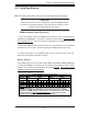
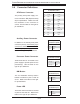
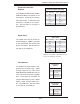
NIC1 LED
The NIC1 (Network Interface Control-
ler) LED connection is located on pins
11 and 12 of JF1. Attach the NIC1
LED cable to display network activity.
Refer to the table on the right for pin
defi nitions.
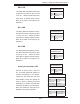
NIC2 LED
The NIC2 (Network Interface Control-
ler) LED connection is located on pins
9 and 10 of JF1. Attach the NIC2
LED cable to display network activity.
Refer to the table on the right for pin
defi nitions.
NIC1 LED
Pin Defi nitions (JF1)
Pin# Defi nition
11 Vcc
12 Ground
NIC2 LED
Pin Defi nitions (JF1)
Pin# Defi nition
9 Vcc
10 Ground
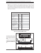
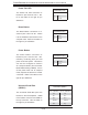
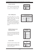
HDD LED
The HDD (IDE Hard Disk Drive) LED
connection is located on pins 13 and
14 of JF1. Attach the IDE hard drive
LED cable to display disk activity.
Refer to the table on the right for pin
defi nitions.
HDD LED
Pin Defi nitions (JF1)
Pin# Defi nition
13 Vcc
14 HD Active
Universal Information LED
Connect an LED to pins 7 and 8 of
JF1 to provide advanced warning of
chassis overheating or fan failure.
These pins also work with the front
UID indicator, which will activate as
either a solid or fl ashing blue LED
depending on whether the LED was
activated via IPMI or the UID button.
Refer to the tables on the right for pin
defi nitions and status indicators.
Universal Info. LED
Pin Defi nitions (JF1)
Pin# Defi nition
7 Vcc
8 Control
Red LED Indications
State Indication
Solid Overheat
Blinking (fast) Fan Fail
Blinking (slow) Power Fail
Blue LED Indications
State Indication
Solid UID (via Button)
Blinking UID (via IPMI)