SUPER ® SUPERSERVER 6016XT-TF SUPERSERVER 6016GT-TF SUPERSERVER 6016GT-TF-TM2 SUPERSERVER 6016GT-TF-TC2 USER’S MANUAL Revision 1.
The information in this User’s Manual has been carefully reviewed and is believed to be accurate. The vendor assumes no responsibility for any inaccuracies that may be contained in this document, makes no commitment to update or to keep current the information in this manual, or to notify any person or organization of the updates. Please Note: For the most up-to-date version of this manual, please see our web site at www.supermicro.com. Super Micro Computer, Inc.
Preface Preface About This Manual This manual is written for professional system integrators and PC technicians. It provides information for the installation and use of the SuperServer 6016XTTF/6016GT-TF/6016GT-TF-TM2/6016GT-TF-TC2. Installation and maintenance should be performed by experienced technicians only. The SuperServer 6016XT-TF/6016GT-TF/6016GT-TF-TM2/6016GT-TF-TC2 is based on the SC818GTQ-1400B 1U rackmount server chassis and the Super X8DTG-DF serverboard.
SUPERSERVER 6016XT-TF/6016GT-TF/TF-TM2/TF-TC2 User's Manual Chapter 5: Advanced Serverboard Setup Chapter 5 provides detailed information on the X8DTG-DF serverboard, including the locations and functions of connectors, headers and jumpers. Refer to this chapter when adding or removing processors or main memory and when reconfiguring the serverboard. Chapter 6: Advanced Chassis Setup Refer to Chapter 6 for detailed information on the SC818GTQ-1400B 1U rackmount server chassis.
Preface Notes v
SUPERSERVER 6016XT-TF/6016GT-TF/TF-TM2/TF-TC2 User's Manual Table of Contents Chapter 1 Introduction 1-1 Overview ......................................................................................................... 1-1 1-2 Serverboard Features ..................................................................................... 1-2 Processors ...................................................................................................... 1-2 Memory ............................................
Table of Contents Installing the Server into a Telco Rack ........................................................... 2-9 2-5 Checking the Serverboard Setup .................................................................. 2-10 2-6 Checking the Drive Bay Setup .......................................................................2-11 Chapter 3 System Interface 3-1 Overview .........................................................................................................
SUPERSERVER 6016XT-TF/6016GT-TF/TF-TM2/TF-TC2 User's Manual Connecting the Control Panel ......................................................................... 5-3 5-4 I/O Ports .......................................................................................................... 5-4 5-5 Installing the Processor and Heatsink ............................................................ 5-5 Installing an LGA1366 Processor ...................................................................
Chapter 1: Introduction Chapter 1 Introduction 1-1 Overview The 6016XT-TF/6016GT-TF/6016GT-TF-TM2/6016GT-TF-TC2 is a GPU-optimized supercomputing server comprised of the SC818GTQ-1400B chassis and the X8DTG-DF serverboard. Please refer to our web site for information on operating systems that have been certified for use with the system (www.supermicro.com). Note: a complete list of safety warnings is provided on the Supermicro web site at http://www.supermicro.com/about/policies/safety_information.
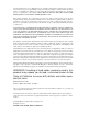
SUPERSERVER 6016XT-TF/6016GT-TF/TF-TM2/TF-TC2 User's Manual 1-2 Serverboard Features At the heart of the SuperServer 6016XT-TF/6016GT-TF/6016GT-TF-TM2/6016GTTF-TC2 lies the X8DTG-DF, a dual processor serverboard based on the Intel 5520 chipset. Below are the main features of the X8DTG-DF. (See Figure 1-1 for a block diagram of the chipset). Processors The X8DTG-DF supports two Intel Xeon processor 5600/5500 series.
Chapter 1: Introduction IPMI IPMI (Intelligent Platform Management Interface) is a hardware-level interface specification that provides remote access, monitoring and administration for Supermicro server platforms. IPMI allows server administrators to view a server’s hardware status remotely, receive an alarm automatically if a failure occurs, and power cycle a system that is non-responsive.
SUPERSERVER 6016XT-TF/6016GT-TF/TF-TM2/TF-TC2 User's Manual from the system fans to efficiently cool the processors and memory. See note on the following page regarding fan control. 1-4 GPU Subsystem The 6016GT family of servers represents Supermicro's line of massively parallel processing dual-GPU servers. Two NVIDIA® Tesla™ GPUs with multiple x16 nonblocking native Gen2 PCI-Express connectivity place these systems at the forefront of today's GPU computing solutions.
Chapter 1: Introduction Figure 1-1. Intel 5520 Chipset: System Block Diagram Note: This is a general block diagram. Please see Chapter 5 for details.
SUPERSERVER 6016XT-TF/6016GT-TF/TF-TM2/TF-TC2 User's Manual 1-5 Contacting Supermicro Headquarters Address: Super Micro Computer, Inc. 980 Rock Ave. San Jose, CA 95131 U.S.A. Tel: +1 (408) 503-8000 Fax: +1 (408) 503-8008 Email: marketing@supermicro.com (General Information) support@supermicro.com (Technical Support) Web Site: www.supermicro.com Europe Address: Super Micro Computer B.V.
Chapter 2: Server Installation Chapter 2 Server Installation 2-1 Overview This chapter provides a quick setup checklist to get your SuperServer up and running. Following these steps in the order given should enable you to have the system operational within a minimum amount of time. This quick setup assumes that your system has come to you with the processors and memory preinstalled. If your system is not already fully integrated with a serverboard, processors, system memory etc.
SUPERSERVER 6016XT-TF/6016GT-TF/TF-TM2/TF-TC2 User's Manual • This product is not suitable for use with visual display work place devices acccording to §2 of the the German Ordinance for Work with Visual Display Units. 2-4 Warnings and Precautions Rack Precautions • Ensure that the leveling jacks on the bottom of the rack are fully extended to the floor with the full weight of the rack resting on them. • • • • In single rack installation, stabilizers should be attached to the rack.
Chapter 2: Server Installation Rack Mounting Considerations Ambient Operating Temperature If installed in a closed or multi-unit rack assembly, the ambient operating temperature of the rack environment may be greater than the ambient temperature of the room. Therefore, consideration should be given to installing the equipment in an environment compatible with the manufacturer’s maximum rated ambient temperature (Tmra).
SUPERSERVER 6016XT-TF/6016GT-TF/TF-TM2/TF-TC2 User's Manual 2-4 Installing the System into a Rack This section provides information on installing the SC818G chassis into a rack unit with the rails provided. There are a variety of rack units on the market, which may mean that the assembly procedure will differ slightly. You should also refer to the installation instructions that came with the rack unit you are using. Note: This rail will fit a rack between 26" and 33.5" deep.
Chapter 2: Server Installation Installing the Inner Rail Extensions The SC818G chassis includes a set of inner rack rails in two sections: inner rails (A) and inner rail extensions (B). The inner rails are preattached and do not interfere with normal use of the chassis if you decide not to install to a server rack. Attaching the inner rail extensions to to the inner rails stabilizes the chassis within the rack. Installing the Inner Rail Extensions 1.
SUPERSERVER 6016XT-TF/6016GT-TF/TF-TM2/TF-TC2 User's Manual Assembling the Outer Rails Each outer rail is in two sections that must be assembled before mounting on to the rack. Assembling the Outer Rails 1. Identify the left and right outer rails by examining the ends, which bend outward. 2. Slide the front section of the outer rail (A), into the rear section of the outer rail (B). Figure 2-3.
Chapter 2: Server Installation Installing the Outer Rails onto the Rack Outer Rail Installation 1. Adjust the outer rails to the proper length so that the outer rail fits snugly within the rack. 2. Align the holes on the front of the outer rail, with the holes on the front of the rack (C) and secure with the screws provided. 3. Align the holes on the rear of the outer rail to the holes on the rack (D) and secure with the screws provided. 4. Repeat the procedure with the second outer rail assembly.
SUPERSERVER 6016XT-TF/6016GT-TF/TF-TM2/TF-TC2 User's Manual Installing the Chassis into a Rack (Figure 2-5) 1. Confirm that chassis includes the inner rails and rail extensions . Also, confirm that the outer rails are installed on the rack. 2. Line chassis rails with the front of the rack rails. 3. Slide the chassis rails into the rack rails, keeping the pressure even on both sides (you may have to depress the locking tabs when inserting).
Chapter 2: Server Installation Installing the Server into a Telco Rack Optional brackets (p/n MCP-290-00016-0N) are needed to install the server to a telco (open type) rack. To install the server into a Telco type rack, use the two L-shaped brackets on either side of the chassis (four total). First, determine how far follow the server will extend out the front of the rack. Larger chassis should be positioned to balance the weight between front and back. If a bezel is included on your server, remove it.
SUPERSERVER 6016XT-TF/6016GT-TF/TF-TM2/TF-TC2 User's Manual 2-5 Checking the Serverboard Setup After you install the server in the rack, you will need to open the unit to make sure the serverboard is properly installed and all the connections have been made. Removing the Chassis Cover (Figure 2-7) 1. Remove the three screws securing the top cover to the chassis. 2. Press both of the release tabs at the same time to release the cover 3. Slide the cover toward the rear of the chassis. 4.
Chapter 2: Server Installation Checking the Components 1. You may have processors already installed to the serverboard. Each processor needs its own heatsink. See Chapter 5 for instructions on processor and heatsink installation. 2. Your server system may have come with system memory already installed. Make sure all DIMMs are fully seated in their slots. For details on adding system memory, refer to Chapter 5. 3. If desired, you can install add-on cards to the system.
SUPERSERVER 6016XT-TF/6016GT-TF/TF-TM2/TF-TC2 User's Manual Providing Power 1. The last thing you must do is to provide input power to the system. Plug the power cord from the power supply unit into a high-quality power strip that offers protection from electrical noise and power surges. It is recommended that you use an uninterruptible power supply (UPS). 2. Finish by depressing the power button on the chassis control panel.
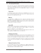
Chapter 3: System Interface Chapter 3 System Interface 3-1 Overview There are several LEDs on the control panel as well as others on the drive carriers to keep you constantly informed of the overall status of the system as well as the activity and health of specific components. There are also two buttons on the chassis control panel and an on/off switch on the power supply. This chapter explains the meanings of all LED indicators and the appropriate response you may need to take.
SUPERSERVER 6016XT-TF/6016GT-TF/TF-TM2/TF-TC2 User's Manual 3-3 Control Panel LEDs The control panel located on the front of the SC818GTQ chassis has five LEDs. These LEDs provide you with critical information related to different parts of the system. This section explains what each LED indicates when illuminated and any corrective action you may need to take. Universal Information LED When this LED blinks red quickly, it indicates a fan failure.
Chapter 3: System Interface 1 NIC1 Indicates network activity on GLAN1 when flashing . HDD This light indicates SATA and/or DVD-ROM drive activity when flashing. Power Indicates power is being supplied to the system's power supply units. This LED should normally be illuminated when the system is operating. 3-4 • • SATA Drive Carrier LEDs Green: Each Serial ATA drive carrier has a green LED. When illuminated, this green LED (on the front of the SATA drive carrier) indicates drive activity.
SUPERSERVER 6016XT-TF/6016GT-TF/TF-TM2/TF-TC2 User's Manual Notes 3-4
Chapter 4: Warning Statements for AC Systems Chapter 4 Standardized Warning Statements for AC Systems 4-1 About Standardized Warning Statements The following statements are industry standard warnings, provided to warn the user of situations which have the potential for bodily injury. Should you have questions or experience difficulty, contact Supermicro's Technical Support department for assistance. Only certified technicians should attempt to install or configure components.
SUPERSERVER 6016XT-TF/6016GT-TF/TF-TM2/TF-TC2 User's Manual Warnung WICHTIGE SICHERHEITSHINWEISE Dieses Warnsymbol bedeutet Gefahr. Sie befinden sich in einer Situation, die zu Verletzungen führen kann. Machen Sie sich vor der Arbeit mit Geräten mit den Gefahren elektrischer Schaltungen und den üblichen Verfahren zur Vorbeugung vor Unfällen vertraut.
Warning Statements for AC Systems . ﺗﺤﺬﻳﺮ!ﻫﺬﺍ ﺍﻟﺮﻣﺰ ﻳﻌﻨﻲ ﺧﻄﺮ ﺍﻧﻚ ﻓﻲ ﺣﺎﻟﺔ ﻳﻤﻜﻦ ﺃﻥ ﺗﺘﺴﺒﺐ ﻓﻲ ﺍﺻﺎﺑﺔ ﺟﺴﺪﻳﺔ ﻛﻦ ﻋﻠﻰ ﻋﻠﻢ ﺑﺎﻟﻤﺨﺎﻁﺮ ﺍﻟﻨﺎﺟﻤﺔ ﻋﻦ ﺍﻟﺪﻭﺍﺋﺮ،ﻗﺒﻞ ﺃﻥ ﺗﻌﻤﻞ ﻋﻠﻰ ﺃﻱ ﻣﻌﺪﺍﺕ ﺍﻟﻜﻬﺮﺑﺎﺋﻴﺔ ﻭﻛﻦ ﻋﻠﻰ ﺩﺭﺍﻳﺔ ﺑﺎﻟﻤﻤﺎﺭﺳﺎﺕ ﺍﻟﻮﻗﺎﺋﻴﺔ ﻟﻤﻨﻊ ﻭﻗﻮﻉ ﺃﻱ ﺣﻮﺍﺩﺙ ﺍﺳﺘﺨﺪﻡ ﺭﻗﻢ ﺍﻟﺒﻴﺎﻥ ﺍﻟﻤﻨﺼﻮﺹ ﻓﻲ ﻧﻬﺎﻳﺔ ﻛﻞ ﺗﺤﺬﻳﺮ ﻟﻠﻌﺜﻮﺭ ﺗﺮﺟﻤﺘﻬﺎ 안전을 위한 주의사항 경고! 이 경고 기호는 위험이 있음을 알려 줍니다. 작업자의 신체에 부상을 야기 할 수 있는 상태에 있게 됩니다. 모든 장비에 대한 작업을 수행하기 전에 전기회로와 관련된 위험요소들을 확인하시고 사전에 사고를 방지할 수 있도록 표준 작업절차를 준수해 주시기 바랍니다.
SUPERSERVER 6016XT-TF/6016GT-TF/TF-TM2/TF-TC2 User's Manual Installation Instructions Warning! Read the installation instructions before connecting the system to the power source. 設置手順書 システムを電源に接続する前に、設置手順書をお読み下さい。 警告 将此系统连接电源前,请先阅读安装说明。 警告 將系統與電源連接前,請先閱讀安裝說明。 Warnung Vor dem Anschließen des Systems an die Stromquelle die Installationsanweisungen lesen. ¡Advertencia! Lea las instrucciones de instalación antes de conectar el sistema a la red de alimentación.
Chapter 4: Warning Statements for AC Systems Circuit Breaker Warning! This product relies on the building's installation for short-circuit (overcurrent) protection. Ensure that the protective device is rated not greater than: 250 V, 20 A.
SUPERSERVER 6016XT-TF/6016GT-TF/TF-TM2/TF-TC2 User's Manual 경고! 이 제품은 전원의 단락(과전류)방지에 대해서 전적으로 건물의 관련 설비에 의존합니다. 보호장치의 정격이 반드시 250V(볼트), 20A(암페어)를 초과하지 않도록 해야 합니다. Waarschuwing Dit product is afhankelijk van de kortsluitbeveiliging (overspanning) van uw electrische installatie. Controleer of het beveiligde aparaat niet groter gedimensioneerd is dan 220V, 20A.
Chapter 4: Warning Statements for AC Systems ¡Advertencia! El sistema debe ser disconnected de todas las fuentes de energía y del cable eléctrico quitado de los módulos de fuente de alimentación antes de tener acceso el interior del chasis para instalar o para quitar componentes de sistema. Attention Le système doit être débranché de toutes les sources de puissance ainsi que de son cordon d'alimentation secteur avant d'accéder à l'intérieur du chassis pour installer ou enlever des composants de systéme.
SUPERSERVER 6016XT-TF/6016GT-TF/TF-TM2/TF-TC2 User's Manual Equipment Installation Warning! Only trained and qualified personnel should be allowed to install, replace, or service this equipment. 機器の設置 トレーニングを受け認定された人だけがこの装置の設置、交換、 またはサービスを許可 されています。 警告 只有经过培训且具有资格的人员才能进行此设备的安装、更换和维修。 警告 只有經過受訓且具資格人員才可安裝、更換與維修此設備。 Warnung Das Installieren, Ersetzen oder Bedienen dieser Ausrüstung sollte nur geschultem, qualifiziertem Personal gestattet werden.
Chapter 4: Warning Statements for AC Systems Waarschuwing Deze apparatuur mag alleen worden geïnstalleerd, vervangen of hersteld door geschoold en gekwalificeerd personeel. Restricted Area Warning! This unit is intended for installation in restricted access areas. A restricted access area can be accessed only through the use of a special tool, lock and key, or other means of security. (This warning does not apply to workstations).
SUPERSERVER 6016XT-TF/6016GT-TF/TF-TM2/TF-TC2 User's Manual אזור עם גישה מוגבלת !אזהרה הגישה ניתנת בעזרת.יש להתקין את היחידה באזורים שיש בהם הגבלת גישה .(' מנעול וכד,כלי אבטחה בלבד )מפתח . ﺗﻢ ﺗﺨﺼﻴﺺ ﻫﺬﻩ ﺍﻟﻮﺣﺪﺓ ﻟﺘﺮﻛﻴﺒﻬﺎ ﻓﻲ ﻣﻨﺎﻁﻖ ﻣﺤﻈﻮﺭﺓ ،ﻳﻤﻜﻦ ﺍﻟﻮﺻﻮﻝ ﺇﻟﻰ ﻣﻨﻄﻘﺔ ﻣﺤﻈﻮﺭﺓ ﻓﻘﻂ ﻣﻦ ﺧﻼﻝ ﺍﺳﺘﺨﺪﺍﻡ ﺃﺩﺍﺓ ﺧﺎﺻﺔ ﻗﻔﻞ ﻭﻣﻔﺘﺎﺡ ﺃﻭ ﺃﻱ ﻭﺳﻴﻠﺔ ﺃﺧﺮﻯ ﻟﻼﻷﻣﺎﻥ 경고! 이 장치는 접근이 제한된 구역에 설치하도록 되어있습니다. 특수도구, 잠금 장치 및 키, 또는 기타 보안 수단을 통해서만 접근 제한 구역에 들어갈 수 있습니다.
Chapter 4: Warning Statements for AC Systems Warnung Bei Einsetzen einer falschen Batterie besteht Explosionsgefahr. Ersetzen Sie die Batterie nur durch den gleichen oder vom Hersteller empfohlenen Batterietyp. Entsorgen Sie die benutzten Batterien nach den Anweisungen des Herstellers. Attention Danger d'explosion si la pile n'est pas remplacée correctement. Ne la remplacer que par une pile de type semblable ou équivalent, recommandée par le fabricant.
SUPERSERVER 6016XT-TF/6016GT-TF/TF-TM2/TF-TC2 User's Manual Redundant Power Supplies Warning! This unit might have more than one power supply connection. All connections must be removed to de-energize the unit. 冗長電源装置 このユニットは複数の電源装置が接続されている場合があります。 ユニットの電源を切るためには、すべての接続を取り外さなければなりません。 警告 此部件连接的电源可能不止一个,必须将所有电源断开才能停止给该部件供电。 警告 此裝置連接的電源可能不只一個,必須切斷所有電源才能停止對該裝置的供電。 Warnung Dieses Gerät kann mehr als eine Stromzufuhr haben.
Chapter 4: Warning Statements for AC Systems .ﻗﺪ ﻳﻜﻮﻥ ﻟﻬﺬﺍ ﺍﻟﺠﻬﺎﺯ ﻋﺪﺓ ﺍﺗﺼﺎﻻﺕ ﺑﻮﺣﺪﺍﺕ ﺍﻣﺪﺍﺩ ﺍﻟﻄﺎﻗﺔ ﻳﺠﺐ ﺇﺯﺍﻟﺔ ﻛﺎﻓﺔ ﺍﻻﺗﺼﺎﻻﺕ ﻟﻌﺰﻝ ﺍﻟﻮﺣﺪﺓ ﻋﻦ ﺍﻟﻜﻬﺮﺑﺎء 경고! 이 장치에는 한 개 이상의 전원 공급 단자가 연결되어 있을 수 있습니다. 이 장치에 전원을 차단하기 위해서는 모든 연결 단자를 제거해야만 합니다. Waarschuwing Deze eenheid kan meer dan één stroomtoevoeraansluiting bevatten. Alle aansluitingen dienen verwijderd te worden om het apparaat stroomloos te maken. Backplane Voltage Warning! Hazardous voltage or energy is present on the backplane when the system is operating.
SUPERSERVER 6016XT-TF/6016GT-TF/TF-TM2/TF-TC2 User's Manual מתח בפנל האחורי !אזהרה יש להיזהר במהלך.קיימת סכנת מתח בפנל האחורי בזמן תפעול המערכת .העבודה ﻫﻨﺎﻙ ﺧﻄﺮ ﻣﻦ ﺍﻟﺘﻴﺎﺭ ﺍﻟﻜﻬﺮﺑﺎﺋﻲ ﺃﻭﺍﻟﻄﺎﻗﺔ ﺍﻟﻤﻮﺟﻮﺩﺓ ﻋﻠﻰ ﺍﻟﻠﻮﺣﺔ ﻋﻨﺪﻣﺎ ﻳﻜﻮﻥ ﺍﻟﻨﻈﺎﻡ ﻳﻌﻤﻞ ﻛﻦ ﺣﺬﺭﺍ ﻋﻨﺪ ﺧﺪﻣﺔ ﻫﺬﺍ ﺍﻟﺠﻬﺎﺯ 경고! 시스템이 동작 중일 때 후면판 (Backplane)에는 위험한 전압이나 에너지가 발생 합니다. 서비스 작업 시 주의하십시오. Waarschuwing Een gevaarlijke spanning of energie is aanwezig op de backplane wanneer het systeem in gebruik is. Voorzichtigheid is geboden tijdens het onderhoud.
Chapter 4: Warning Statements for AC Systems Attention L'équipement doit être installé conformément aux normes électriques nationales et locales. תיאום חוקי החשמל הארצי !אזהרה .התקנת הציוד חייבת להיות תואמת לחוקי החשמל המקומיים והארציים ﺗﺮﻛﻴﺐ ﺍﻟﻤﻌﺪﺍﺕ ﺍﻟﻜﻬﺮﺑﺎﺋﻴﺔ ﻳﺠﺐ ﺃﻥ ﻳﻤﺘﺜﻞ ﻟﻠﻘﻮﺍﻧﻴﻦ ﺍﻟﻤﺤﻠﻴﺔ ﻭﺍﻟﻮﻁﻨﻴﺔ ﺍﻟﻤﺘﻌﻠﻘﺔ ﺑﺎﻟﻜﻬﺮﺑﺎء 경고! 현 지역 및 국가의 전기 규정에 따라 장비를 설치해야 합니다. Waarschuwing Bij installatie van de apparatuur moet worden voldaan aan de lokale en nationale elektriciteitsvoorschriften.
SUPERSERVER 6016XT-TF/6016GT-TF/TF-TM2/TF-TC2 User's Manual ¡Advertencia! Al deshacerse por completo de este producto debe seguir todas las leyes y reglamentos nacionales. Attention La mise au rebut ou le recyclage de ce produit sont généralement soumis à des lois et/ou directives de respect de l'environnement. Renseignez-vous auprès de l'organisme compétent. סילוק המוצר !אזהרה .
Chapter 4: Warning Statements for AC Systems 警告 當您從機架移除風扇裝置,風扇可能仍在轉動。小心不要將手指、螺絲起子和其他 物品太靠近風扇。 Warnung Die Lüfter drehen sich u. U. noch, wenn die Lüfterbaugruppe aus dem Chassis genommen wird. Halten Sie Finger, Schraubendreher und andere Gegenstände von den Öffnungen des Lüftergehäuses entfernt. ¡Advertencia! Los ventiladores podran dar vuelta cuando usted quite ell montaje del ventilador del chasis.
SUPERSERVER 6016XT-TF/6016GT-TF/TF-TM2/TF-TC2 User's Manual Power Cable and AC Adapter Warning! When installing the product, use the provided or designated connection cables, power cables and AC adaptors. Using any other cables and adaptors could cause a malfunction or a fire. Electrical Appliance and Material Safety Law prohibits the use of UL or CSA -certified cables (that have UL/CSA shown on the code) for any other electrical devices than products designated by Supermicro only.
Chapter 4: Warning Statements for AC Systems Attention Lors de l'installation du produit, utilisez les bables de connection fournis ou désigné. L'utilisation d'autres cables et adaptateurs peut provoquer un dysfonctionnement ou un incendie. Appareils électroménagers et de loi sur la sécurité Matériel interdit l'utilisation de UL ou CSA câbles certifiés qui ont UL ou CSA indiqué sur le code pour tous les autres appareils électriques que les produits désignés par Supermicro seulement.
SUPERSERVER 6016XT-TF/6016GT-TF/TF-TM2/TF-TC2 User's Manual Notes 4-20
Chapter 5: Advanced Serverboard Setup Chapter 5 Advanced Serverboard Setup This chapter covers the steps required to install the X8DTG-DF serverboard into the chassis, connect the data and power cables and install add-on cards. All serverboard jumpers and connections are also described. A layout and quick reference chart are included in this chapter for your reference. Remember to completely close the chassis when you have finished working with the serverboard to better cool and protect the system.
SUPERSERVER 6016XT-TF/6016GT-TF/TF-TM2/TF-TC2 User's Manual Unpacking The serverboard is shipped in antistatic packaging to avoid electrical static discharge. When unpacking the board, make sure the person handling it is static protected. 5-2 Serverboard Installation This section explains the first step of physically mounting the X8DTG-DF into the SC818GTQ-1400 chassis. Following the steps in the order given will eliminate the most common problems encountered in such an installation.
Chapter 5: Advanced Serverboard Setup 5-3 Connecting Cables Now that the serverboard is installed, the next step is to connect the cables to the board. These include the data (ribbon) cables for the peripherals and control panel and the power cables. Connecting Data Cables The ribbon cables used to transfer data from the peripheral devices have been carefully routed to prevent them from blocking the flow of cooling air that moves through the system from front to back.
SUPERSERVER 6016XT-TF/6016GT-TF/TF-TM2/TF-TC2 User's Manual Figure 5-1. Control Panel Header Pins 20 19 Ground No Connection x (Key) x (Key) Power On LED 3.3V HDD LED FP UID/3.3V Stby NIC1 LED (Link) NIC1 LED (Activity) NIC2 LED (Link) NIC2 LED (Activity) OH/Fan Fail/PWR Fail/UID LED Blue LED (UID Cathode)/5V Stby PWR Fail LED 3.3V Ground Reset (Button) Ground Power (Button) 2 5-4 1 I/O Ports The I/O ports are color coded in conformance with the PC 99 specification.
Chapter 5: Advanced Serverboard Setup 5-5 Installing the Processor and Heatsink Warning! Avoid placing direct pressure to the top of the processor package. Always remove the power cord first before adding, removing or changing any hardware components. Notes: • Always connect the power cord last and always remove it before adding, removing or changing any hardware components. Make sure that you install the processor into the CPU socket before you install the CPU heatsink.
SUPERSERVER 6016XT-TF/6016GT-TF/TF-TM2/TF-TC2 User's Manual CPU 1. After removing the plastic cap, use your thumb and the index finger to hold the CPU at the north and south center edges. 2. Align the CPU key (the semi-circle cutout) with the socket key (the notch below the gold color dot on the side of the socket). CPU Socket 3. Once the CPU and the socket are aligned, carefully lower the CPU straight down into the socket.
Chapter 5: Advanced Serverboard Setup Installing a CPU Heatsink 1. Remove power from the system and unplug the AC power cord from the power supply. 2. Do not apply any thermal grease to the heatsink or the CPU die; the required amount has already been applied. 3. Place the heatsink on top of the CPU so that the four mounting holes are aligned with those on the (preinstalled) heatsink retention mechanism. 4. Screw in two diagonal screws (i.e. the #1 and the #2 screws) until just snug.
SUPERSERVER 6016XT-TF/6016GT-TF/TF-TM2/TF-TC2 User's Manual 5-6 Installing Memory CAUTION! Exercise extreme care when installing or removing DIMM modules to prevent any possible damage. Memory Support The X8DTG-DF supports up to 192 GB of registered ECC or up to 48 GB of unbuffered ECC/non-ECC DDR3-1333/1066/800 MHz SDRAM in 12 DIMM slots. See the following table for memory installation. Notes: With unbuffered ECC/non-ECC memory, 2 GB is the maximum DIMM size that can be supported per slot.
Chapter 5: Advanced Serverboard Setup DIMM Population Table DIMM Slots per Channel DIMMs Populated per Channel DIMM Type (Reg.= Registered) Speeds (in MHz) Ranks per DIMM (any combination; SR=Single Rank, DR=Dual Rank, QR=Quad Rank) 2 1 Reg. DDR3 ECC 800,1066,1333 SR or DR 2 1 Reg. DDR3 ECC 800,1066 QR 2 2 Reg. DDR3 ECC 800,1066 Mixing SR, DR 2 2 Reg. DDR3 ECC 800 Mixing SR, DR,QR Notes: Due to OS limitations, some operating systems may not show more than 4 GB of memory.
SUPERSERVER 6016XT-TF/6016GT-TF/TF-TM2/TF-TC2 User's Manual Populating DIMMs for Optimal Performance For One CPU (CPU1) Installed Branch 0 3 DIMMs P1 DIMM1A Branch 1 P1 DIMM2A Branch 2 P1 DIMM3A Populating DIMMs for Optimal Performance For One CPU (CPU2) Installed Branch 0 3 DIMMs P2 DIMM1A Branch 1 P2 DIMM2A Branch 2 P2 DIMM3A Populating DIMMs for Optimal Performance For Two CPUs Installed CPU1 Branch 0 6 DIMMs 5-6 P1-DIMM1A CPU2 Branch 1 Branch 2 Branch 0 Branch 1 P1-DIMM2A P1-DIMM3A P2
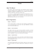
Chapter 5: Advanced Serverboard Setup 5-7 Serverboard Details Figure 5-5. X8DTG-DF Layout (not drawn to scale) VGA COM1 LE4 USB0/1 SW1 LAN1 LAN2 IPMI_LAN IPMB JBMC1 JPG1 JPL1 Winbond 450R BMC SBX 2A JTPM1 LE2 J_UID_OW JSPK1 SBX 1A JWD1 JNMI1 Intel 82576 LAN CTRL PCI-E 2.0 x4 JBT1 Intel ICH10R (South Bridge) BIOS Intel 5520 IOH-36D SATA5 X8DTG-DF SATA4 Rev. 2.
SUPERSERVER 6016XT-TF/6016GT-TF/TF-TM2/TF-TC2 User's Manual X8DTG-DF Quick Reference Jumper Description Default Setting JBMC1* BMC (Baseboard Management CTRL) Enable Pins 1-2 (Enabled) JBT1 CMOS Clear (See Section 5-9) JPG1 VGA Enable Pins 1-2 (Enabled) JPL1 LAN1/2 Enable Pins 1-2 (Enabled) J_UID_OW Red LED OW (Pins 7/8 of JF1) Off (Overwrites) JWD1 Watch Dog Pins 1-2 (Reset) Connector Description COM1 COM1 Serial Port FAN 1-8 System/CPU Fan Headers IPMB IPMB Header (for an IPMI
Chapter 5: Advanced Serverboard Setup 5-8 Connector Definitions 20-pin Main Power Connector Pin Definitions Main ATX Power Supply Connector Pin# Definition Pin # Definition 11 PS On 1 Ground The primary power supply connector 12 5VSB 2 Ground (JPW1) is a proprietary design. Refer to 13 Ground 3 Ground the table on the right for the pin definitions 14 Ground 4 Ground of this connector.
SUPERSERVER 6016XT-TF/6016GT-TF/TF-TM2/TF-TC2 User's Manual Reset Connector Reset Button Pin Definitions (JF1) The reset connector is located on pins 3 and 4 of JF1 and attaches to the reset Pin# Definition switch on the computer chassis. See the 3 Reset table on the right for pin definitions. 4 Ground PWR Fail LED Pin Definitions (JF1) Power Fail LED The Power Fail LED connection is located on pins 5 and 6 of JF1. Refer to the table Pin# Definition 5 3.3V on the right for pin definitions.
Chapter 5: Advanced Serverboard Setup HDD/FP UID Button The HDD/UID button connections are located on pins 13/14 of JF1. Attach a hard-drive LED cable to display HDD or SATA activity. This connection can also be HDD/UID LED Pin Definitions (JF1) used for the front panel UID (Unit Identifier) button. (The UID LED on pin 7 of JF1 Pin# Definition 13 UID Signal/3.3V works in conjunction with the UID button.
SUPERSERVER 6016XT-TF/6016GT-TF/TF-TM2/TF-TC2 User's Manual LAN1/2 (Ethernet Ports) Two Ethernet ports (designated LAN1 and LAN2) are located beside the VGA port on the I/O backplane. These ports accept RJ45 type cables. Universal Serial Bus (USB) Universal Serial Bus Pin Definitions There are two Universal Serial Bus ports located on the I/O panel and two additional Pin # USB headers located on the serverboard.
Chapter 5: Advanced Serverboard Setup PWRI2C Pin Definitions PWR I2C Connector Pin# This System Management Bus (I2C) connector is used to monitor the status of the power supply. See the table on the right for pin definitions. Definition 1 Clock 2 Data 3 PWR Fail 4 Ground IPMB Header Pin Definitions IPMB A System Management Bus header for the IPMI is located at IPMB. Connect the appropriate cable here to use the IPMB I2C connection on your system.
SUPERSERVER 6016XT-TF/6016GT-TF/TF-TM2/TF-TC2 User's Manual Internal Speaker Internal Speaker Pin Definitions Attach a speaker to the JSPK1 pins to provide audible alarms for the beep Pin# codes. See the table on the right for pin definitions. Definitions Pin 1 Pos. (+) Beep In Pin 2 Neg.
Chapter 5: Advanced Serverboard Setup 5-9 Jumper Settings Explanation of Jumpers To modify the operation of the serverboard, jumpers can be used to choose between optional settings. 3 2 1 3 2 1 Connector Pins Jumpers create shorts between two pins to change the function of the connector. Pin 1 is identified with a square Jumper solder pad on the printed circuit board. See the serverboard layout pages for jumper locations.
SUPERSERVER 6016XT-TF/6016GT-TF/TF-TM2/TF-TC2 User's Manual LAN1/2 Enable/Disable LAN1/2 Enable/Disable Jumper Settings Change the setting of jumper JPL1 to enable or disable the LAN1/LAN2 Ethernet Jumper Setting ports on the serverboard. See the table on Pins 1-2 Enabled Pins 2-3 Disabled the right for jumper settings. The default setting is enabled. Definition Watch Dog Enable/Disable JWD controls the Watch Dog function.
Chapter 5: Advanced Serverboard Setup BMC Enable/Disable BMC Enable/Disable Jumper Settings Use jumper JPBMC1 to enable or disable the Winbond WPCM450 BMC (Baseboard Both Jumpers Definition Management Controller), which supports Pins 1-2 Enabled IPMI 2.0. See the table on the right for Pins 2-3 Disabled jumper settings. 5-10 Onboard Indicators LAN1/2 LEDs The Ethernet ports have two LEDs.
SUPERSERVER 6016XT-TF/6016GT-TF/TF-TM2/TF-TC2 User's Manual 5-11 SATA Ports SATA Port Pin Definitions SATA Ports There are no jumpers to configure the onboard SATA connectors. See the table on the right for pin definitions.
Chapter 5: Advanced Serverboard Setup 5-12 Installing Software After the hardware has been installed, you should first install the operating system and then the drivers. The necessary drivers are all included on the Supermicro CDs that came packaged with your system. Driver/Tool Installation Display Screen Note: Click the icons showing a hand writing on paper to view the readme files for each item.
SUPERSERVER 6016XT-TF/6016GT-TF/TF-TM2/TF-TC2 User's Manual Supero Doctor III The Supero Doctor III program is a web-based management tool that supports remote management capability. It includes Remote and Local Management tools. The local management is called SD III Client. The Supero Doctor III program included on the CD-ROM that came with your motherboard allows you to monitor the environment and operations of your system.
Chapter 5: Advanced Serverboard Setup Supero Doctor III Interface Display Screen (Remote Control) Note: SD III Software Revision 1.0 can be downloaded from our Web Site at: ftp:// ftp.supermicro.com/utility/Supero_Doctor_III/. You can also download the SDIII User's Guide at: http://www.supermicro.com/manuals/other/SDIII_User_Guide.pdf. For Linux, we will recommend using Supero Doctor II.
SUPERSERVER 6016XT-TF/6016GT-TF/TF-TM2/TF-TC2 User's Manual Notes 5-26
Chapter 6: Advanced Chassis Setup Chapter 6 Advanced Chassis Setup This chapter covers the steps required to install components and perform maintenance on the SC818GTQ chassis. For component installation, follow the steps in the order given to eliminate the most common problems encountered. If some steps are unnecessary, skip ahead to the next step. Tools Required: The only tool you will need to install components and perform maintenance is a Philips screwdriver.
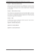
SUPERSERVER 6016XT-TF/6016GT-TF/TF-TM2/TF-TC2 User's Manual Figure 6-1. Chassis: Front and Rear Views Power Supply Control Panel Hot-Swap Drive Bays (3)* USB Ports PCI Slot Dedicated IPMI LAN Port LAN Ports COM Port VGA Port *An optional solution is available to provide six 2.5" drive bays instead of the standard three 3.5" drive bays.
Chapter 6: Advanced Chassis Setup System Fan Failure Fan speed is controlled by system temperature via a BIOS setting. If a fan fails, the remaining fans will ramp up to full speed. Replace any failed fan at your earliest convenience with the same type and model (the system can continue to run with a failed fan). Replacing a System Fan (Figure 6-2) 1.
SUPERSERVER 6016XT-TF/6016GT-TF/TF-TM2/TF-TC2 User's Manual Figure 6-2. Removing a Fan from the Fan Tray 6-4 Drive Bay Installation/Removal Accessing the Drive Bays Hard Drives: Because of their hotswap capability, you do not need to access the inside of the chassis or power down the system to install or replace hard drives. Proceed to the next section for instructions. Peripheral Drives: The SC818GTQ chassis includes space for a variety of peripheral drive options, including a 2.
Chapter 6: Advanced Chassis Setup 12 1 Figure 6-3. Removing a Hard Drive Carrier Warning: Except for short periods of time (swapping hard drives), do not operate the server with the hard drive carriers removed.
SUPERSERVER 6016XT-TF/6016GT-TF/TF-TM2/TF-TC2 User's Manual Installing a Hard Drive to the Hard Drive Carrier 1. Remove the two screws securing the dummy drive to the carrier. 2. Remove the dummy drive from the carrier. 3. Install a new drive into the carrier with the printed circuit board side facing downward so that the mounting holes align with those in the carrier. 4. Secure the hard drive by tightening all six screws. Installing a Hard Drive Carrier Into the Chassis 1.
Chapter 6: Advanced Chassis Setup Note: When installing the hard drive carrier that is next to the power supply, the power supply handle must be lifted before extending the hard drive carrier handle, or before inserting the hard drive carrier into the drive bay. Figure 6-5. Installing/Removing the Carrier Next to the Power Supply Peripheral Drive Installation Installing or Replacing a Peripheral Drive 1. Unplug the main power cord to the chassis. 2.
SUPERSERVER 6016XT-TF/6016GT-TF/TF-TM2/TF-TC2 User's Manual 6-5 Installing the Air Shroud Air shrouds concentrate airflow to maximize fan efficiency. The air shroud for the SC818GTQ chassis does not require screws to set up. Installing the Air Shroud 1. Position the air shroud in the chassis as illustrated above. 2. Align the notch (A) on the air shroud with the pin (B) on the add-on card bracket. 3. Slide the pin (B) into the back of the notch (A) 4.
Chapter 6: Advanced Chassis Setup 6-6 Power Supply The system includes a single 1400 watt power supply, which is auto-switching capable. Power must be removed from the system when replacing the power supply. Power Supply Failure If the power supply module fails, the system will shut down and you will need to replace the module. Replacements can be ordered directly from Supermicro (see contact information in the Preface).
SUPERSERVER 6016XT-TF/6016GT-TF/TF-TM2/TF-TC2 User's Manual Notes 6-10
Chapter 7: BIOS Chapter 7 BIOS 7-1 Introduction This chapter describes the AMI BIOS Setup Utility for the X8DTG-DF. The AMI ROM BIOS is stored in a Flash EEPROM and can be easily updated. This chapter describes the basic navigation of the AMI BIOS Setup Utility setup screens. Starting BIOS Setup Utility To enter the AMI BIOS Setup Utility screens, press the key while the system is booting up. Note: In most cases, the key is used to invoke the AMI BIOS setup screen.
SUPERSERVER 6016XT-TF/6016GT-TF/TF-TM2/TF-TC2 User's Manual Starting the Setup Utility Normally, the only visible Power-On Self-Test (POST) routine is the memory test. As the memory is being tested, press the key to enter the main menu of the AMI BIOS Setup Utility. From the main menu, you can access the other setup screens. An AMI BIOS identification string is displayed at the left bottom corner of the screen below the copyright message.
Chapter 7: BIOS Supermicro X8DTG-DF • BIOS Build Version: This item displays the BIOS revision used in your system. • BIOS Build Date: This item displays the date when this BIOS was completed. • AMI BIOS Core Version: This item displays the revision number of the AMI BIOS Core upon which your BIOS was built. Processor The AMI BIOS will automatically display the status of the processor used in your system: • CPU Type: This item displays the type of CPU used in the motherboard.
SUPERSERVER 6016XT-TF/6016GT-TF/TF-TM2/TF-TC2 User's Manual 7-3 Advanced Setup Configurations Use the arrow keys to select Boot Setup and hit to access the submenu items: BOOT Features Quick Boot If Enabled, this option will skip certain tests during POST to reduce the time needed for system boot. The options are Enabled and Disabled. Quiet Boot This option allows the bootup screen options to be modified between POST messages or the OEM logo. Select Disabled to display the POST messages.
Chapter 7: BIOS Hit 'Del' Message Display This feature displays "Press DEL to run Setup" during POST. The options are Enabled and Disabled. Interrupt 19 Capture Interrupt 19 is the software interrupt that handles the boot disk function. When this item is set to Enabled, the ROM BIOS of the host adaptors will "capture" Interrupt 19 at boot and allow the drives that are attached to these host adaptors to function as bootable disks.
SUPERSERVER 6016XT-TF/6016GT-TF/TF-TM2/TF-TC2 User's Manual C1E Support Select Enabled to use the feature of Enhanced Halt State. C1E significantly reduces the CPU's power consumption by reducing the CPU's clock cycle and voltage during a "Halt State." The options are Disabled and Enabled.
Chapter 7: BIOS tion and heat dissipation. Please refer to Intel’s web site for detailed information. The options are Disable (Disable GV3) and Enable (Enable GV3). Intel® TurboMode Technology Select Enabled to use the Turbo Mode to boost system performance. The options are Enabled and Disabled. Intel® C-STATE Tech If enabled, C-State is set by the system automatically to either C2, C3 or C4 state. The options are Disabled and Enabled.
SUPERSERVER 6016XT-TF/6016GT-TF/TF-TM2/TF-TC2 User's Manual QPI L0s and L1 This enables the QPI power state to low power. L0s and L1 are automatically selected by the motherboard. The options are Disabled and Enabled. Memory Frequency This feature forces a DDR3 frequency slower than what the system has detected. The available options are Auto, Force DDR-800, Force DDR-1066, and Force DDR-1333. Memory Mode The options are Independent, Channel Mirror, Lockstep and Sparing.
Chapter 7: BIOS Guardband Temperature This is the temperature which applies to the DIMM temperature threshold. Each step is in 0.5oC increment. The default is [006]. Press "+" or "-" on your keyboard to change this value. Inlet Temperature This is the temperature detected at the chassis inlet. Each step is in 0.5oC increment. The default is [070]. Press "+" or "-" on your keyboard to change this value. Temperature Rise This is the temperature rise to the DIMM thermal zone. Each step is in 0.5oC increment.
SUPERSERVER 6016XT-TF/6016GT-TF/TF-TM2/TF-TC2 User's Manual Intel VT-d Select Enabled to enable Intel's Virtualization Technology support for Direct I/O VT-d by reporting the I/O device assignments to VMM through the DMAR ACPI Tables. This feature offers fully-protected I/O resource-sharing across the Intel platforms, providing the user with greater reliability, security and availability in networking and data-sharing. The settings are Enabled and Disabled.
Chapter 7: BIOS Hand-Off support. When enabled, the EHCI Interface will be changed from the BIOScontrolled to the OS-controlled. The options are Disabled and Enabled. IDE/SATA/Floppy Configuration When this submenu is selected, the AMI BIOS automatically detects the presence of the IDE devices and displays the following items: SATA#1 Configuration If Compatible is selected, it sets SATA#1 to legacy compatibility mode, while selecting Enhanced sets SATA#1 to native SATA mode.
SUPERSERVER 6016XT-TF/6016GT-TF/TF-TM2/TF-TC2 User's Manual Primary IDE Master/Slave, Secondary IDE Master/Slave, Third IDE Master, and Fourth IDE Master These settings allow the user to set the parameters of Primary IDE Master/Slave, Secondary IDE Master/Slave, Third and Fourth IDE Master slots. Hit to activate the following submenu screen for detailed options of these items. Set the correct configurations accordingly.
Chapter 7: BIOS Select 4 to allow the AMI BIOS to use PIO mode 4. It has a data transfer bandwidth of 32-Bits. Select Enabled to enable 32-Bit data transfer. DMA Mode Select Auto to allow the BIOS to automatically detect IDE DMA mode when the IDE disk drive support cannot be determined. Select SWDMA0 to allow the BIOS to use Single Word DMA mode 0. It has a data transfer rate of 2.1 MBs. Select SWDMA1 to allow the BIOS to use Single Word DMA mode 1. It has a data transfer rate of 4.2 MBs.
SUPERSERVER 6016XT-TF/6016GT-TF/TF-TM2/TF-TC2 User's Manual the S.M.A.R.T. Select Enabled to allow the AMI BIOS to use the S.M.A.R.T. to support hard drive disk. The options are Disabled, Enabled, and Auto. 32Bit Data Transfer Select Enable to enable the function of 32-bit IDE data transfer. The options are Enabled and Disabled. IDE Detect Timeout (sec) Use this feature to set the time-out value for the BIOS to detect the ATA, ATAPI devices installed in the system.
Chapter 7: BIOS as its I/O port address and IRQ 4 for the interrupt address. The options for Serial Port1 are Disabled, 3F8/IRQ4, 3E8/IRQ4, 2E8/IRQ3. The options for Serial Port2 are Disabled, 2F8/IRQ3, 3E8/IRQ4, and 2E8/IRQ3. Remote Access Configuration Remote Access This allows the user to enable the Remote Access feature. The options are Disabled and Enabled.
SUPERSERVER 6016XT-TF/6016GT-TF/TF-TM2/TF-TC2 User's Manual Hardware Health Monitor This feature allows the user to monitor system health and review the status of each item as displayed. CPU Overheat Alarm This option allows the user to select the CPU Overheat Alarm setting which determines when the CPU OH alarm will be activated to provide warning of possible CPU overheat. Warning! 1.
Chapter 7: BIOS Supermicro has leveraged this feature by assigning a temperature status to certain thermal conditions in the processor (Low, Medium and High). This makes it easier for the user to understand the CPU’s temperature status, rather than by just simply seeing a temperature reading (i.e., 25oC). The CPU Temperature feature will display the CPU temperature status as detected by the BIOS: Low – This level is considered as the ‘normal’ operating state.
SUPERSERVER 6016XT-TF/6016GT-TF/TF-TM2/TF-TC2 User's Manual Fan1 ~ Fan 4 Reading This feature displays the fan speed readings from fan interfaces Fan1 through Fan5. CPU1 Vcore, CPU2 Vcore, +5Vin, +12Vcc (V), VP1 DIMM, VP2 DIMM, 3.3Vcc (V), and Battery Voltage ACPI Configuration Use this feature to configure Advanced Configuration and Power Interface (ACPI) power management settings for your system. ACPI Version Features The options are ACPI v1.0, ACPI v2.0 and ACPI v3.0.
Chapter 7: BIOS Status of BMC Baseboard Management Controller (BMC) manages the interface between system management software and platform hardware. This is an informational feature which returns the status code of the BMC micro controller. View BMC System Event Log This feature displays the BMC System Event Log (SEL). It shows the total number of entries of BMC System Events. To view an event, select an Entry Number and pressing to display the information as shown in the screen.
SUPERSERVER 6016XT-TF/6016GT-TF/TF-TM2/TF-TC2 User's Manual • Total Number of Entries • SEL Entry Number • SEL Record ID • SEL Record Type • Timestamp, Generator ID • Event Message Format User • Event Sensor Type • Event Sensor Number, • Event Dir Type • Event Data. Clear BMC System Event Log Clear BMC System Log Select OK and press the key to clear the BMC system log. Select Cancel to keep the BMC System log. The options are OK and Cancel.
Chapter 7: BIOS Channel Number - Enter the channel number for the SET LAN Config command. This is initially set to [1]. Press "+" or "-" on your keyboard to change the Channel Number. Channel Number Status - This feature returns the channel status for the Channel Number selected above: "Channel Number is OK" or "Wrong Channel Number". IP Address Configuration Enter the IP address for this machine. This should be in decimal and in dotted quad form (i.e., 192.168.10.253).
SUPERSERVER 6016XT-TF/6016GT-TF/TF-TM2/TF-TC2 User's Manual Parameter Selector Use this feature to select the parameter of your IP Address configuration. IP Address The BIOS will automatically enter the IP address of this machine; however it may be over-ridden. IP addresses are 6 two-digit hexadecimal numbers (Base 16, 0 ~ 9, A, B, C, D, E, F) separated by dots. (i.e., 00.30.48.D0.D4.60). Current IP Address in BMC This item displays the current IP address used for your IPMI connection.
Chapter 7: BIOS SEL PEF Configuration Set PEF Configuration Set this feature to configure the Platform Event Filter (PEF). PEF interprets BMC events and performs actions based on pre-determined settings or 'traps' under IPMI 1.5 specifications. For example, powering the system down or sending an alert when a triggering event is detected. The following will appear if PEF Support is set to Enabled. The default is Disabled. PEF Action Global Control - These are the different actions based on BMC events.
SUPERSERVER 6016XT-TF/6016GT-TF/TF-TM2/TF-TC2 User's Manual Event Message for PEF Action - This enables of disables Event Messages for PEF action. Refer to Table 24.6 of the IPMI 1.5 Specification for more information at www.intel.com. The options are Disabled and Enabled. BMC Watch Dog Timer Action Allows the BMC to reset or power down the system if the operating system hangs or crashes. The options are Disabled, Reset System, Power Down, Power Cycle.
Chapter 7: BIOS 7-4 Security Settings The AMI BIOS provides a Supervisor and a User password. If you use both passwords, the Supervisor password must be set first. Supervisor Password This item indicates if a Supervisor password has been entered for the system. "Not Installed" means a Supervisor password has not been used. User Password This item indicates if a user password has been entered for the system. "Not Installed" means that a user password has not been used.
SUPERSERVER 6016XT-TF/6016GT-TF/TF-TM2/TF-TC2 User's Manual Clear User Password (Available only when User Password has been set) This item allows you to clear a user password after it has been entered. Password Check This item allows you to check a password after it has been entered. The options are Setup and Always.
Chapter 7: BIOS Hard Disk Drives This feature allows the user to specify the boot sequence from all available hard disk drives. The settings are Disabled and a list of all hard disk drives that have been detected (i.e., 1st Drive, 2nd Drive, 3rd Drive, etc). • 1st Drive - [SATA: XXXXXXXXX] Removable Drives This feature allows the user to specify the boot sequence from available Removable Drives. The settings are 1st boot device, 2nd boot device, and Disabled.
SUPERSERVER 6016XT-TF/6016GT-TF/TF-TM2/TF-TC2 User's Manual Save Changes and Exit When you have completed the system configuration changes, select this option to leave the BIOS Setup Utility and reboot the computer, so the new system configuration parameters can take effect. Select Save Changes and Exit from the Exit menu and press . Discard Changes and Exit Select this option to quit the BIOS Setup without making any permanent changes to the system configuration, and reboot the computer.
Appendix A: BIOS Error Beep Codes Appendix A BIOS Error Beep Codes During the POST (Power-On Self-Test) routines, which are performed each time the system is powered on, errors may occur. Non-fatal errors are those which, in most cases, allow the system to continue the boot-up process. The error messages normally appear on the screen. Fatal errors are those which will not allow the system to continue the boot-up procedure.
SUPERSERVER 6016XT-TF/6016GT-TF/TF-TM2/TF-TC2 User's Manual Notes A-2
Appendix B: Installing Windows Appendix B Installing Windows After all hardware components have been installed, you must first configure Intel South Bridge RAID Settings before you install the Windows OS and other software drivers. To configure RAID settings, please refer to RAID Configuration User Guides posted on our web site at www.supermicro.com/support/manuals. Note: the following instructions apply to installing Windows 7/XP or Windows 2003 only.
SUPERSERVER 6016XT-TF/6016GT-TF/TF-TM2/TF-TC2 User's Manual B-2 Installing Windows for a Non-RAID System 1. Insert Microsoft's Windows 7/XP/Windows 2003 setup CD in the CD drive and the system will start booting up from the CD. 2. Continue with the OS installation. The Windows OS Setup screen will display. 3. From the Windows setup screen, press the key. The XP/2003 Setup will automatically load all device files and then continue with the installation. 4.
Appendix C: System Specifications Appendix C System Specifications Processors Two Intel Xeon 5600/5500 series processors Note: Please refer to our web site for a complete listing of supported processors. Chipset Intel 5520 + ICH10R BIOS 32 Mb AMIBIOS® SPI Flash ROM Memory Capacity Twelve DIMM sockets supporting up to 192 GB of registered ECC DDR31333/1066/800 SDRAM or up to 48 GB of unbuffered ECC/non-ECC DDR31333/1066/800 MHz SDRAM Note: See the memory section in Chapter 5 for details.
SUPERSERVER 6016XT-TF/6016GT-TF/TF-TM2/TF-TC2 User's Manual 6016GT-TF-TC2: one low-profile PCI-E x4 card Serverboard X8DTG-DF (proprietary ATX form factor) Dimensions: 16.64" x 7.74" (423 x 197 mm) Chassis SC818GTQ-1400B (1U rackmount) Dimensions: (WxHxD) 17.2 x 1.7 x 28.2 in. (437 x 43 x 716 mm) Weight Gross (Bare Bone): 47 lbs. (21.4 kg.
Appendix C: System Specifications Electromagnetic Immunity: EN 55024/CISPR 24, (EN 61000-4-2, EN 61000-43, EN 61000-4-4, EN 61000-4-5, EN 61000-4-6, EN 61000-4-8, EN 61000-411) Safety: CSA/EN/IEC/UL 60950-1 Compliant, UL or CSA Listed (USA and Canada), CE Marking (Europe) California Best Management Practices Regulations for Perchlorate Materials: This Perchlorate warning applies only to products containing CR (Manganese Dioxide) Lithium coin cells. “Perchlorate Material-special handling may apply. See www.
SUPERSERVER 6016XT-TF/6016GT-TF/TF-TM2/TF-TC2 User's Manual (continued from front) The products sold by Supermicro are not intended for and will not be used in life support systems, medical equipment, nuclear facilities or systems, aircraft, aircraft devices, aircraft/emergency communication devices or other critical systems whose failure to perform be reasonably expected to result in significant injury or loss of life or catastrophic property damage.