
User's Manual

5-14
SUPERSERVER 6016XT-TF/6016GT-TF/TF-TM2/TF-TC2 User's Manual
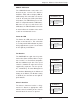
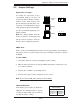
NIC2 LED
Pin Defi nitions (JF1)
Pin# Defi nition
9 Vcc
10 Ground
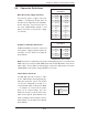
NIC2 (JLAN2) LED
The LED connections for JLAN2 are on
pins 9 and 10 of JF1. Attach an LED cable
to display network activity. See the table on
the right for pin defi nitions.
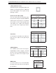
NIC1 LED
Pin Defi nitions (JF1)
Pin# Defi nition
11 Vcc
12 Ground
NIC1 (JLAN1) LED
The LED connections for JLAN1 are on
pins 11 and 12 of JF1. Attach an LED cable
to display network activity. See the table on
the right for pin defi nitions.
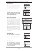
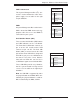
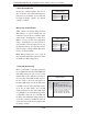
Overheat/Fan Fail/UID LED
Connect an LED cable to pins 7 and 8 of
JF1 for the Overheat/Fan Fail and UID
LED connections. The red LED (pin 8)
provides warning of an overheat or fan
failure. The blue LED (pin 7) works as
the UID LED indicator for the front panel
UID button located on pins 13~14 of JF1.
When Jumper J_UID_OW is set to off
(default), the red LED takes precedence
over the blue LED. (See Page 3-2 for
details.) Refer to the table on the right for
pin defi nitions.
OH/Fan Fail/Blue_UID LED Pin
Defi nitions (JF1)
Pin# Defi nition
7 Blue_LED-Cathode(UID)/5.5V.SB
8 OH/Fan Fail/UID LED (Red)
OH/Fan Fail LED Status
(Red LED)
State Defi nition
Off Normal
On Overheat
Flashing Fan Fail
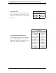
Power Fail LED
The Power Fail LED connection is located
on pins 5 and 6 of JF1. Refer to the table
on the right for pin defi nitions.
PWR Fail LED
Pin Defi nitions (JF1)
Pin# Defi nition
5 3.3V
6 PWR Fail LED
Reset Connector
The reset connector is located on pins 3
and 4 of JF1 and attaches to the reset
switch on the computer chassis. See the
table on the right for pin defi nitions.
Reset Button
Pin Defi nitions (JF1)
Pin# Defi nition
3 Reset
4 Ground