
User's Manual

Chapter 5: Advanced Serverboard Setup
5-17
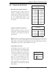
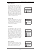
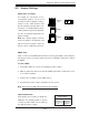
IPMB
A System Management Bus header for the
IPMI is located at IPMB. Connect the ap-
propriate cable here to use the IPMB I
2
C
connection on your system.
IPMB Header
Pin Defi nitions
Pin# Defi nition
1 Data
2 Ground
3 Clock
4 No Connection
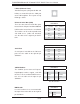
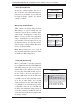
PWR I
2
C Connector
This System Management Bus (I
2
C) con-
nector is used to monitor the status of the
power supply. See the table on the right
for pin defi nitions.
PWRI2C
Pin Defi nitions
Pin# Defi nition
1 Clock
2 Data
3 PWR Fail
4 Ground
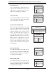
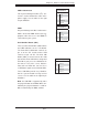
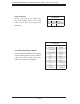
Unit Identifi er Button (SW1)
There are two Unit Identifi er (UID) buttons
and LED indicators on the serverboard.
The Front Panel UID button connects to
pin 13 on the JF1 header and its LED
connects to pin 7 of JF1. The Rear UID
button (SW1) is located next to the VGA
port and the Rear UID LED is designated
LE4. When you press the UID button on
the front or rear of the server, both the
front and rear LEDs will turn on. Press
a UID button again to turn off both LEDs.
These UID LEDs provide easy identifi ca-
tion of a system located in a large rack of
servers. See the table on the right for pin
defi nitions.
Note: the UID LED is supported by either
the physical button or the BMC. When con-
trolled by the physical button it is solid on.
When controlled by the BMC, it blinks.
UID Button
Pin# Defi nition
1 Ground
2 Ground
3 Button In
4 Ground