
Data Sheet

7366R-041906-4
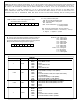
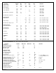
ABSOLUTE MAXIMUM RATINGS:
(All voltages referenced to Vss)
Parameter Symbol Values Unit
DC Supply Voltage VDD +7.0 V
Input Voltage VIN Vss - 0.3 to VDD + 0.3 V
Operating Temperature TA -25 to +80
o
C
Storage Temperature TSTG 65 to +150
o
C
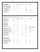
MDR1. The MDR1 (Mode Register 1) is an 8-bit read/write register which is appended to MDR0 for additional modes.
Upon power-up MDR1 is cleared to zero.
B7 B6 B5 B4 B3 B2 B1 B0
B1 B0 = 00: 4-byte counter mode
= 01: 3-byte counter mode
= 10: 2-byte counter mode.
= 11: 1-byte counter mode
B2 = 0: Enable counting
= 1: Disable counting
B3 = : not used
B4 = 0: NOP
= 1: FLAG on IDX (B4 of STR)
B5 = 0: NOP
= 1: FLAG on CMP (B5 of STR)
B6 = 0: NOP
= 1: FLAG on BW (B6 of STR)
B7 = 0: NOP
= 1: FLAG on CY (B7 of STR)
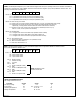
MDR0. The MDR0 (Mode Register 0) is an 8-bit read/write register that sets up the operating mode for the LS7366R. The MDR0 is
written into by executing the "write-to-MDR0" instruction via the instruction register. Upon power up MDR0 is cleared to zero. The
following is a breakdown of the MDR bits:
B7 B6 B5 B4 B3 B2 B1 B0
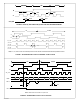
B1 B0 = 00: non-quadrature count mode. (A = clock, B = direction).
= 01: x1 quadrature count mode (one count per quadrature cycle).
= 10: x2 quadrature count mode (two counts per quadrature cycle).
= 11: x4 quadrature count mode (four counts per quadrature cycle).
B3 B2 = 00: free-running count mode.
= 01: single-cycle count mode (counter disabled with carry or borrow, re-enabled with reset or load).
= 10: range-limit count mode (up and down count-ranges are limited between DTR and zero,
respectively; counting freezes at these limits but resumes when direction reverses).
= 11: modulo-n count mode (input count clock frequency is divided by a factor of (n+1),
where n = DTR, in both up and down directions).
B5 B4 = 00: disable index.
= 01: configure index as the "load CNTR" input (transfers DTR to CNTR).
= 10: configure index as the "reset CNTR" input (clears CNTR to 0).
= 11: configure index as the "load OTR" input (transfers CNTR to OTR).
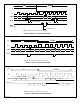
B6 = 0: Asynchronous Index
= 1: Synchronous Index (overridden in non-quadrature mode)
B7 = 0: Filter clock division factor = 1
= 1: Filter clock division factor = 2
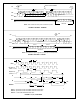
NOTE: Applicable to both
LFLAG/ and DFLAG/