
Data Sheet
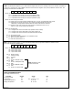
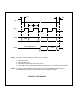

Note 1. The SPI port of the host MCU must be set up as follows:
1. SPI master mode.
2. SCK idle state = low
3. Clock edge for MOSI data shift = high to low
4. Clock edge for input data (MISO) sample by the Processor = low to high (or bit middle)
Note 2. To conform with the multibyte transmission protocol of LS7366R, the SS/ output port
of the MCU may require direct manipulation by the application program.
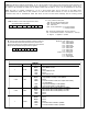
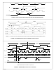
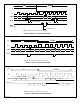
FIGURE 2. SPI TIMINGS
7366R-041906-7
tCSH
t
CL
tCH
tCSL
MSB
LSB
SS/
SCK
MOSI
MISO
HIGH IMPEDANCE
(
)
(
)
(
)
(
)
(
)
(
)
(
)
(
)