
Manual

4WD & 6WD Wheelchair ATR
SuperDroid Robots, Inc Contact
224 Technology Park Lane (919) 557-9162
Fuquay Varina, NC 27526 SDR@SDRobots.com
www.SuperDroidRobots.com
Revised: February 8, 2019 Page 10 of 11
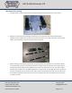
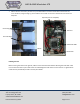
Electrical Assembly
For electrical assembly please follow the schematic for your selected motor controller at the link below:
Schematics
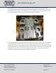
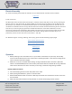
A note on wire size:
The wheelchair motors are 24V motors that will pull a maximum of about 70A (stall current). Start by choosing the
wire size. From our wire gauge table, we know 12 AWG can only take 41A. If we double up the 12 AWG wire (use
two wires per run), however, it can take 82A. Another option is to use 8 AWG gauge which can take 73A. You can
use whatever combination of wire as long it will take more than 70A. We recommend oversizing the wire so know it
won’t burn up. So we are going to go with two 12 AWG wires. Because of the cable combination, we need
overcurrent protection that trips between 70A and 82A. If we choose overcurrent protection higher than the cable
can hold, the wires will burn, and the protection will never actuate. If we go lower, the motors may cut out
prematurely. So we’ll use two auto reset circuit breakers – 24V, 40A.
For additional support on wiring, soldering, and crimping, please read the following support pages:
Electric Motor Hookup Support
Electric Power Hookup Support
Soldering Tips
Crimping Wires
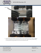
Operation
1. Before powering on the robot make sure it is up on blocks so the wheels can spin freely. Occasionally
some or all of the wheels start as soon as the motor controller gets power. In this case the settings of the
motor controller need to be changed.
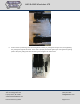
2. Make sure to use the correct DIP switch settings. If using a Sabertooth motor controller in R/C mode
switch 1 should be DOWN (closest to the number) and all other switches should be UP. If using a different
mode see the manual for the motor controller you are using on Dimension Engineering’s website.
Binding a Spektrum Remote
3. Insert the bind plug into the receiver and power on the robot.
4. While pressing the Bind button, power on the transmitter.
5. Release the Bind button after the receiver’s LED stays illuminated. This indicates the receiver is bound to
the transmitter.
6. While the robot and transmitter are still powered on, remove the bind plug from the receiver.