
Manual


4WD & 6WD Wheelchair ATR
SuperDroid Robots, Inc Contact
224 Technology Park Lane (919) 557-9162
Fuquay Varina, NC 27526 SDR@SDRobots.com
www.SuperDroidRobots.com
Revised: February 8, 2019 Page 5 of 11
Mechanical Assembly
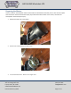
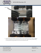
1. Align the motors as shown below, with the shaft facing inward and toward the front of the chassis.
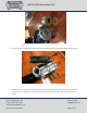
2. Mount the motors with the socket head screws that you removed from them along with the washers
provided in the kit. Tighten but not all the way so that the motors can still slide in the slots. The chains will
need to be tensioned later on by moving the motors in the slots.
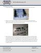
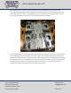
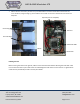
3. Mount bearings on the bottom of the chassis using the provided 3/8” hardware. Then slide all the wheels
into the bearings, making sure to slide the #35 wheel coupling sprockets (and keys) on the shaft between
the beaings as shown below. Do not tighten the set screws in the bearings yet as you may need to adjust
positioning of the shafts later. The 6WD configuration is shown below. For the 4WD robot, there will only be
one #35 15 tooth sprocket per wheel (4 total). Next, slide the #40 sprockets with keys onto the ends of the
drive shafts and align them with the chain slots. You can tighten set screws on sprockets but you may have
to adjust them later.