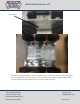
4WD & 6WD Wheelchair ATR Assembly and Operation Follow this manual for assembly of the 4WD WC ATR and the 6WD WC ATR, as well as the 4WD and 6WD snowplow. The pictures in this manual are taken from any of these assemblies so the robot you receive may look a little different than the robots in the pictures. The assembly steps, however, are the same.
4WD & 6WD Wheelchair ATR Contents Preparing the Motors ................................................................................................................................................... 3 Mechanical Assembly ................................................................................................................................................... 5 Electrical Assembly ....................................................................................................................
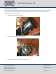
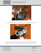
4WD & 6WD Wheelchair ATR Preparing the Motors There is a brake on the wheelchair motors that should be removed before assembly. There is also aluminum plate that needs to be removed. Follow these steps (If you selected to add encoders on the motors, the brake has already been removed. Skip to step 5.): 1. Remove the back cover of the motor 2. Remove the brake by taking out two screws. 3. Cut the two white wires. These are no longer used.
WD & 6WD Wheelchair ATR 4. Cut the connector off the motor and remove the two white wires by pulling them through the wire jacket. 5. Remove the six socket head screws holding the aluminum plate to the bottom of the motor. Remove the aluminum plate, it will not be used. Set the screws aside, these will be used to mount the motors to the chassis. SuperDroid Robots, Inc 224 Technology Park Lane Fuquay Varina, NC 27526 www.SuperDroidRobots.com Contact (919) 557-9162 SDR@SDRobots.
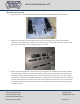
4WD & 6WD Wheelchair ATR Mechanical Assembly 1. Align the motors as shown below, with the shaft facing inward and toward the front of the chassis. 2. Mount the motors with the socket head screws that you removed from them along with the washers provided in the kit. Tighten but not all the way so that the motors can still slide in the slots. The chains will need to be tensioned later on by moving the motors in the slots. 3. Mount bearings on the bottom of the chassis using the provided 3/8” hardware.
4WD & 6WD Wheelchair ATR For the 6WD robot, you may have to shim the bearings so that all wheels touch the ground so after mounting bearings and before installing the sprockets, slide the wheel axles into the bearings (with wheels mounted) and turn the robot over on the wheels to check if the wheels are all touching the ground. Shim the bearings as necessary. There are shims for 4 bearings provided, if necessary. 4. Couple the wheels with the provided #35 chain and connecting links.
4WD & 6WD Wheelchair ATR Chain Guard 5. Slide the #40 10 tooth sprockets on the motor shafts, line them up with the slots in the chassis, and tighten the set screws. Measure and cut the #40 chain to fit around the motor and drive wheel sprockets, making sure the sprockets are aligned and the chain is clear of the sides of the slots. SuperDroid Robots, Inc 224 Technology Park Lane Fuquay Varina, NC 27526 www.SuperDroidRobots.com Contact (919) 557-9162 SDR@SDRobots.
4WD & 6WD Wheelchair ATR 6. Tension chain by loosening motor mounting bolts, screwing in jacking bolts and jam nuts, and tightening the jacking bolts against the motor. Once chain is properly tensioned, tighten jam nuts against the jacking plate to keep the jacking bolts from loosening then retighten the motor bolts. SuperDroid Robots, Inc 224 Technology Park Lane Fuquay Varina, NC 27526 www.SuperDroidRobots.com Contact (919) 557-9162 SDR@SDRobots.
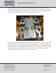
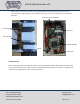
4WD & 6WD Wheelchair ATR 7. Mount batteries with battery brackets and provided hardware as shown below. Mount electronics box, circuit breakers, and grounding lug as well. Mount items shown in electronics box below to the aluminum backplate. Syren 10 (used in snowplow) Ground Lug Solenoid Circuit breakers Sabertooth 2x60 Switch RC Receiver Inflating the tires Before running the robot on the ground, make sure the tires have been inflated.
4WD & 6WD Wheelchair ATR Electrical Assembly For electrical assembly please follow the schematic for your selected motor controller at the link below: Schematics A note on wire size: The wheelchair motors are 24V motors that will pull a maximum of about 70A (stall current). Start by choosing the wire size. From our wire gauge table, we know 12 AWG can only take 41A. If we double up the 12 AWG wire (use two wires per run), however, it can take 82A. Another option is to use 8 AWG gauge which can take 73A.
4WD & 6WD Wheelchair ATR 7. If the wheel aren’t moving as desired, it may be necessary to swap the Alieron and Elevator plugs or to reverse the channels on the transmitter. To reverse channels see the instructions for “Servo Reversing” in the Spektrum documentation. General Terms 1.