INSTALLATION INSTRUCTIONS STANDARD SERIES 36" Wood Burning Fireplaces P/N 700,040M REV. A 02/2008 MODELS BR-36 BRI-36 BR-36-2 BC-36 BCI-36 BC-36-2 This installation manual will enable you to obtain a safe, efficient and dependable installation of your fireplace system. Please read and understand these instructions before beginning your installation. Do not alter or modify the fireplace or its components under any circumstances.
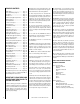
TABLE OF CONTENTS Safety Rules .................................... page Tools and Building Supplies ............ page Precautions ..................................... page Introduction ..................................... page Clearances/Height Requirements ..... page Chimney System ............................. page Assembly Outline ............................. page Location of Fireplace ....................... page Assembly Steps ............................... page Preinstallation Notes .............
PRECAUTIONS Note: These fireplace systems are not difficult to install. However, in the interest of safety, it is recommended that the installer be a qualified or certified “tradesman” familiar with commonly accepted fireplace installation and safety techniques as well as prevailing local codes.
Insulate Joists Same As Ceiling Draft Stops Chimney Height LOCATION OF FIREPLACE The total height of your completed fireplace system from the surface the fireplace rests on to the chimney top must not exceed 60' and must also meet minimum height requirements. Refer to the minimum system height chart. Carefully select the proper location for heat circulation, aesthetics, chimney obstructions and clearance to side wall(s).
ASSEMBLY STEPS Note: The following steps represent the normal sequence of installation. Each installation is unique, however, and might require a different sequence. 1. Position firebox prior to framing or into prepared framing. 2. Install the chimney system. 3. Connect house wiring to the fireplace for later attachment of optional blower. 4. Install optional outside combustion air kit. 5. Plumb gas line if a decorative gas appliance will be used.
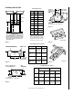
FIREPLACE SPECIFICATIONS 1-1/2" (38 mm) 7-1/2" (191 mm) 9-5/8" (244 mm) 36" (914 mm) 1-1/2" Metal Safety Strips 37" (940 mm) 20-3/16" (513 mm) 27-7/8" (708 mm) 2" (51 mm) Figure 8 7-3/16" (183 mm) 40" (1016 mm) 43" (1092 mm) Blocking Front (BC Model Shown) Appliance Top Spacer Metal Safety Strips Figure 9 Step 3. Refer to fireplace drawings and specifications on pages 6 and 7 for framing dimensions and details. Frame appliance enclosure as illustrated in Figures 11 through 14 on page 8.
FRAMING SPECIFICATIONS Framing Dimensions (See Note) Header *B2 B1 A Fireplace Framing *Note: When Framing With 6” Studs Header Must Be 17” (432mm) Higher. Use Security Chimney’s OR15 Offset/Return Elbow To Recess The Chimney Back 2 1/2” (64mm). Flat Frame Down To A False Header At (B1). Maintain Required Clearance To Chimney At All Times.
Step 4. Fireplace should be fastened to side framing members using the nailing tabs at the top and bottom of the fireplace front face. Use 8d nails or equivalent (Figure 17 ). 8d Nail Or Equivalent Fastener Figure 17 For Canadian Installations Proceed with Steps 5 through 8 Step 5. Attach the cold climate kit, Model FTF8-CCK1-LD, around the chimney collar with the screws provided (see Figure 18 ). Note: CCK1-LD model requires a 6" diameter Class 0 metallic air duct, acquired locally by installer.
CHIMNEY 30° OFFSET THROUGH FLOOR OR CEILING It may be necessary to assemble the chimney at 30° when passing through the floor or ceiling area. Use the F8FS30 firestop spacer as shown in Figures 22 and 23. Support the chimney at floor or ceiling penetration with a FTF8 stabilizer if distance of chimney below ceiling is 10' or more. Maintain 1"* minimum air space to combustibles from chimney sections. Attic Space F8FS30-2 Firestop Spacer 2" Min. Air Space FTF8-S4 Stabilizer 2" Min. Air Space 10' Max.
Roof Ridge FTF8-S4 Stabilizer Figure 28 120° Note: Do not apply excessive pressure to any subsequent chimney sections following the stabilizer when installing. Ensure each subsequent chimney section is securely attached by testing as noted in Step 4. Step 6. Select the proper Security Chimneys roof flashing based on pitch of roof.
To determine the number of chimney sections and chimney components required, follow these steps: Less Than 10' 2' Min. 3' Min 10' 3' Min 1. Determine total vertical height of the fireplace installation. This dimension is the distance from the surface the fireplace sets on to the point where smoke exits from the termination. 2. Determine the number of chimney components required, except chimney sections. This would include firestop spacers, stabilizers, roof flashing, etc. 3.
The offset and return elbows may be attached together, or a section or sections of chimney may be used between, but do not exceed 20' in total length between elbows. If sections of pipe exceed 10' between elbows, a chimney stabilizer must be used at the midpoint (Figure 36 ). The stabilizer support straps must be attached under tension (in shear) to structural framing members above. When two sets of elbows are used, the maximum combined length of chimney used between elbows cannot exceed 20' (Figure 37 ).
OFFSET ELEVATION CHART A1 Return Elbow 20' Max. B1 Stabilizer 10' Max.
Step 1. Determine the offset distance where chimney is to pass through the first ceilingdimension “A.” To find this point on your ceiling, first determine the center point for a vertical chimney following the instructions for vertical installation. et Scr Eve ews ry Re Joi qu nt ired Pa st At 6' Joints Chimney Section No Joi Scre nts ws Fo Re r F qu irs ire t6 dI 'o n fO ffs 4' 6' No. 8 x 1/2" SMS Measure height to the ceiling from the top of fireplace-dimension “B.
POWER TO THE FIREPLACE The Optional Blower Kit Operates on 115 volt 60 Hz 150 watts AC HOUSE WIRING GROUND WIRE House Wiring Must Be Secured With The Appropriate Electrical Connector To The Fireplace Convenience Outlet Wiring WARNING: DO NOT REMOVE THE ACTUATOR ARM LOCKING SCREW UNLESS THE COMPLETE OUTSIDE AIR VENT SYSTEM HAS BEEN INSTALLED IN ACCORDANCE WITH THE DETAILED INSTRUCTIONS PROVIDED WITH THE KIT.
If you’re installing a gas line, connect it before the fireplace is framed and enclosed in the finished wall. The gas knockout is determined by the indentation located at the bottom and slightly off center in the side refractories. THE KNOCKOUT IS ALWAYS REMOVED FROM INSIDE THE FIREPLACE. DO NOT REMOVE THE KNOCKOUT UNLESS YOU ARE INSTALLING A GAS LINE. If removal is attempted from the outer wrapper, side refractory damage may occur. With a medium-sized hammer, lightly tap the surface of the indentation.
Hearth Extension Dimensions A 16" B 35" C 8" D 51" C Note: To convert inches to millimeters divide by 0.03937 C B A D Figure 47 Methods of Determining Hearth Extension and Wall Shield Equivalents - To determine the thickness required for the alternate material when either the “k” value or “r” value is known, use either the k formula or r formula.
Wall Shield Required Where Less Than 12" The sum of all “R values” is: .70 + .10 +. 038 + .10 = .938 This would NOT be an acceptable combination of material for the hearth extension since the total calculated “R value” of the materials used is under the required “R value” of 1.19. An additional layer of insulating materials must be used. 24" 30" Note: Also see NFI Certification Manuals for expanded explanation on calculating “R values” when multiple materials are used.
INSTALLATION COMPONENTS The following items are available for use in the installation of this appliance.
INSTALLATION COMPONENTS Chase Termination (Square) 63L51 FTF8-CT2 Chase Termination (Round) 63L45 FTF8-CTDT Chase Termination (Square) 63L48 FTF8-CT1 Locking Band 63L60 FLB Attic Shield Assembly 63L67 FTF8-FSAS** **Note: 2" clearance required for Canadian Installation - as applicable. The manufacturer reserves the right to make changes at any time, without notice, in design, materials, specifications, prices and also to discontinue colors, styles and products.