
Extra Information


H07023980 / DT2000532-02
English
INSTALLATION
DT2032734-0
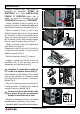
A
B
Fig. 1
7
1
7
1
DT2032736-0
D
C
Fig. 3
4
5
Fig. 5
DT2032741-0
7
6
E
F
Fig. 4
Fig. 2
DT2012193-00
DT2032735-00
DT2032739-01
- Remove the right side panel following the
instructions given in the par. “REMOVING
THE CLADDING” in the instruction booklet
“INSTALLATION, USE AND MAINTENANCE”
accompanying the product or the cap.
“INSTALLATION” in the “CLADDING” instruction
booklet.
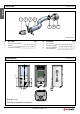
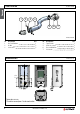
- Proceed with removing the primary air shutter
[A] to be found in the pipe on the right side of
the stove, having loosened the relative fastening
screw [B]. (Fig. 1)
- Fit the Ø 40 mm union elbow [1] connected to
the flexible pipe [4], to be found in the kit, onto
the primary air inlet pipe, aligning the hole in the
elbow with the hole in the primary air inlet pipe.
Using the self-tapping screw [7] provided in
the kit, fasten the union elbow. (Fig. 2)
- Remove the rear panel [C] from the stove, having
loosened the relative screws.
Remove the knockout [D] as shown in the figure,
taking care not to scratch or dent it. (Fig. 3)
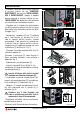
- Refit the rear panel [C].
- Insert the connector Ø 60 mm [6] of the
combustion air kit into the hole just created in the
panel [C].
Align the slots in the connector [6] with the holes
to be found in the rear panel [C] and fasten the
connector using the self-tapping screws [7]
provided in the kit. (Fig. 4)
- Connect up the connector and the union elbow
previously fastened to the stove, locking the hose
with the clip [5] provided in the kit. (Fig. 5)
- Refit the previously removed cladding in the
reverse order to removal.
- Connect the stove to any fresh air intake.
Insert the end of the connector with the
smallest diameter inside the stove [E].
Check that the hose does not come into
contact with moving parts of the stove
during operation.
5