www.DanaherMotion.
Danaher Motion Superior Electric Record of Manual Revisions ISSUE Date Description of Revision G 09/12/2003 Updated corporate information Copyright Information Copyright 1992 - 2003 Danaher Motion - All rights reserved. Printed in the United States of America. NOTICE: Not for use or disclosure outside of Danaher Motion except under written agreement. All rights are reserved.
Danaher Motion Superior Electric Safety Safety symbols used in this manual are: Warning Alerts users to potential physical danger or harm. Failure to follow warning notices could result in personal injury or death. Caution Directs attention to general precautions, which if not followed, could result in personal injury and/or equipment damage. Note Highlights information critical to your understanding or use of the product.
Danaher Motion Superior Electric THE FOREGOING WARRANTY IS IN LIEU OF ANY OTHER WARRANTIES, EXPRESS OR IMPLIED, INCLUDING, WITHOUT LIMITATION, ANY IMPLIED WARRANTY OF MERCHANTABILITY OR FITNESS FOR A PARTICULAR PURPOSE, and of any other obligations or liabilities on the part of the Company; and no person is authorized to assume for the Company any other liability with respect to equipment manufactured by the Company. The Company shall have no liability with respect to equipment not of its manufacture.
Danaher Motion Superior Electric Table of Contents SECTION 1: INTRODUCTION.................................................................................... 6 1.1 USING THIS MANUAL .............................................................................................. 6 1.2 PRODUCT FEATURES ............................................................................................... 6 SECTION 2: EXPRESS START UP ............................................................................
Danaher Motion Superior Electric SECTION 1: INTRODUCTION 1.1 USING THIS MANUAL ® It is important that you understand how this SLO-SYN 2000MD4 Translator/Drive is installed and operated before you attempt to use it. Read this manual completely before proceeding with the installation of this unit. This manual is an installation and operating guide to the SLO-SYN 2000MD4 Translator/Drive. Section 1 gives an overview of the Drive and its features.
Danaher Motion Superior Electric SECTION 2: EXPRESS START UP The following instructions define the minimum steps necessary to make your Drive operational. Always disconnect the AC power to the unit and be certain the "PWR ON" LED is OFF before connecting or disconnecting the motor leads. FAILURE TO DO THIS RESULTS IN A SHOCK HAZARD. Always operate the Motor and the Drive GROUNDED. Be sure to twist together the wires for each motor phase. Six twists per foot is a good guideline. 1. 2. 3. 4. 5.
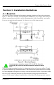
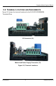
Danaher Motion Superior Electric Section 3: Installation Guidelines 3.1 MOUNTING The SLO-SYN Drive is mounted by fastening its mounting brackets to a flat surface as shown in Figure 3.1. If the drive assembly is mounted against a bulkhead, be sure to apply a thin coating of thermal compound between the drive and the mounting surface before fastening the unit in place. Do not use too much thermal compound. It is better to use too little than too much. Figure 3.
Danaher Motion Superior Electric 3.2 TERMINAL LOCATIONS AND ASSIGNMENTS Figure 3.2 shows the terminal locations for the SLO-SYN SS2000MD4 Translator/Drive. I/O Connector (J2) Motor And Power Supply Connector (J1) Figure 3.
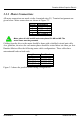
Danaher Motion Superior Electric 3.3.1 Motor Connections All motor connections are made via the 6-terminal strip (J1). Terminal assignments are given below. Motor connections are shown in Figure 3.3. J1 Pin 1 2 3 4 Assignment M1 (Phase A+) M3 (Phase A-) M4 (Phase B+) M5 (Phase B-) Motor phase A is M1 and M3 and motor phase B is M4 and M5. The motor frame must be grounded. Cabling from the drive to the motor should be done with a shielded, twisted pair cable.
Danaher Motion Superior Electric MOTOR TERMINAL "M" NUMBERS MOTOR MOTOR CONNECTOR PIN CONNECTOR PIN DRIVE PIN 1 RED B 1 5 D DRIVE PIN 2 WHITE/ RED H 3 4 F * N.C. DRIVE PIN 2 RED B BLACK G WHITE/ RED H 1 5 2 6 3 4 DRIVE PIN 4 BLACK DRIVE PIN 3 GREEN 4-LEAD MOTORS DRIVE PIN 1 WHITE/ BLACK DRIVE PIN 4 D GREEN E WHITE F WHITE/ GREEN DRIVE PIN 3 DRIVE PIN 4 N.C.
Danaher Motion Superior Electric 3.3.2 Power Input The DC input power is connected to terminals 5 and 6 of the terminal strip (J1). Terminal 5 [Vm(+)] is the power supply plus (+) connection and pin 6 [Vom(-)] is the power supply minus (-) connection. An unregulated supply similar to that shown in Figure 3.4 is preferable. If a regulated supply is used, it must be capable of operating with the added filter capacitor. A switching regulated supply may not be suitable for use with this drive.
Danaher Motion Superior Electric SECTION 4: SPECIFICATIONS 4.1 MECHANICAL Size (Inches) 1.56 H x 4.13 W x 3.25 D (mm) 40 H x 105 W x 83 D 0.6 pounds (272 grams) Weight 4.2 ELECTRICAL DC Input Range............ 24 VDC min., 40 VDC max. DC Current ................... see Motor Table Drive Power Dissipation (Worse Case) ..... 35 watts 4.3 ENVIRONMENTAL Temperature Operating +32° F to +122° F (0° C to +50° C) free air ambient, Natural Convection.
Danaher Motion Superior Electric MOTORS FOR USE WITH THE SS2000MD4 TRANSLATOR/DRIVE Power Supply Current Standstill Maximum (Amps. DC) (Amps. DC) Motor Winding M061 08 Series 2.5 1.0 2.0 M061 08 Parallel 3.5 1.0 2.0 M062 09 Series 3.0 1.0 2.5 M062 09 Parallel 3.5 1.0 3.5 M063 09 Series 3.0 1.5 2.0 M063 09 Parallel 3.5 1.0 3.5 M091 09 Series 3.0 1.0 1.5 M091 09 Parallel 3.5 1.0 3.0 M092 09 Series 3.0 1.5 2.0 M092 09 Parallel 3.5 1.0 3.0 - - 2.
Danaher Motion Superior Electric 4.5 CURRENT SETTINGS The proper current setting for each motor is shown on the individual torque vs. speed curves. Use this current level to obtain the torque shown. Switches 1 through 7 select the current level. Select the desired operating current by setting the appropriate switch to position 1 (ON). The OFF position is labeled "0". Only one switch should be ON. If two or more switches are ON, the one that selects the highest current level is the active switch.
Danaher Motion Superior Electric 4.7 SIGNAL SPECIFICATIONS 4.7.1 Connector Pin Assignments All connections are made via the 4-pin terminal strip (J2). Pin 1 2 3 4 Assignment OPTO PULSE DIR AWO 4.7.2 Signal Descriptions OPTO Opto-Isolator Supply User supplied power for the opto-isolators. PULSE Pulse Input A low to high transition on this pin advances the motor one step. The step size is determined by the Step Resolution switch setting.
Danaher Motion Superior Electric 4.7.4 Timing Requirements PULSE Max. Frequency....... 20 kHz Max. Rise and Fall Times ................ 1 microsecond Min. Pulse Width ....................... 25 microseconds Other Signals Response Time ....... 25 microseconds OPTO IN 12 VDC, 16 mA PER SIGNAL 560 ohms PULSE CONTROL SIGNAL 1/4 watt DRIVE CONTROL LOGIC COMMON OPTO IN 4.5 - 6.0 VDC, 16 mA PER SIGNAL PULSE CONTROL SIGNAL DRIVE CONTROL LOGIC COMMON OPTO IN 4.5 - 6.
Danaher Motion Superior Electric SECTION 5: TORQUE VERSUS SPEED CHARACTERISTICS 5.1 MOTOR PERFORMANCE All stepper motors exhibit instability at their natural frequency and harmonics of that frequency. Typically, this instability occurs at speeds between 50 and 1000 full steps per second and, depending on the dynamic motor load parameters, cause excessive velocity modulation or improper positioning. This type of instability is represented by the open area at the low end of each Torque vs. Speed curve.
Danaher Motion Superior Electric 5.2 TYPICAL TORQUE VERSUS SPEED CURVES The test conditions used when obtaining the torque versus speed data are listed in the lower left-hand corner of each curve.
Danaher Motion Superior Electric SS2000MD4 20 400030-043 Rev G
Danaher Motion Superior Electric SS2000MD4 21 400030-043 Rev G
Danaher Motion Superior Electric SS2000MD4 22 400030-043 Rev G
Danaher Motion Superior Electric SS2000MD4 23 400030-043 Rev G
Danaher Motion Superior Electric SS2000MD4 24 400030-043 Rev G
Danaher Motion Superior Electric SS2000MD4 25 400030-043 Rev G
Danaher Motion Superior Electric SS2000MD4 26 400030-043 Rev G
Danaher Motion Superior Electric SS2000MD4 27 400030-043 Rev G
Danaher Motion Superior Electric SS2000MD4 28 400030-043 Rev G
Danaher Motion Superior Electric SS2000MD4 29 400030-043 Rev G
Danaher Motion Superior Electric SS2000MD4 30 400030-043 Rev G
Danaher Motion Superior Electric SS2000MD4 31 400030-043 Rev G
Danaher Motion Superior Electric SS2000MD4 32 400030-043 Rev G
Danaher Motion Superior Electric SS2000MD4 33 400030-043 Rev G
Danaher Motion Superior Electric SS2000MD4 34 400030-043 Rev G
Danaher Motion Superior Electric SECTION 6: SYSTEM CHECKING Motors connected to this drive can develop high torque and large amounts of mechanical energy. Keep clear of the motor shaft and all parts mechanically linked to the motor shaft. Turn off all power to the drive before performing work on parts mechanically coupled to the motor. If installation and operating instructions have been carefully followed, this unit should perform correctly.
Danaher Motion Superior Electric APPENDIX A: TROUBLESHOOTING A.1 ELECTRICAL INTERFERENCE PROBLEMS Electrical interference problems are common with today’s computer-based controls. Such problems are often difficult to diagnose and cure. If such a problem occurs with your system, it is recommended that the following checks be made to locate the cause of the problem. 1. Check the quality of the AC line voltage using an oscilloscope and a line monitor.