
Installation Manual

18
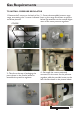
STEP 6: VISUAL CHECKS
Before reinstalling the bottom panel, the
following visual check must be performed
to ensure that the conversion has been
carried out properly and without damage
to other components of the range.
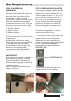
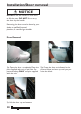
BURNER IGNITER AND
THERMOCOUPLE POSITION
The appropriate gap between the tip of
the spark plug or thermocouple and the
burner shall be approximately 1/8’’.
The tip of the spark plug or
thermocouple must fully overlap at
least the rst gas emission hole of the
burner. After performing all these
visual checks, reinstall the bottom
panel of the oven compartment and
proceed to setting the minimum for
each burner.
Gas Requirements
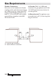
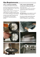
STEP 7: MINIMUM
FLAME ADJUSTMENT
WARNING! These adjustments should
be made only for use of the appliance
with natural gas. For use with liquid
propane gas, the By-pass screw must be
fully turned in a clockwise direction.
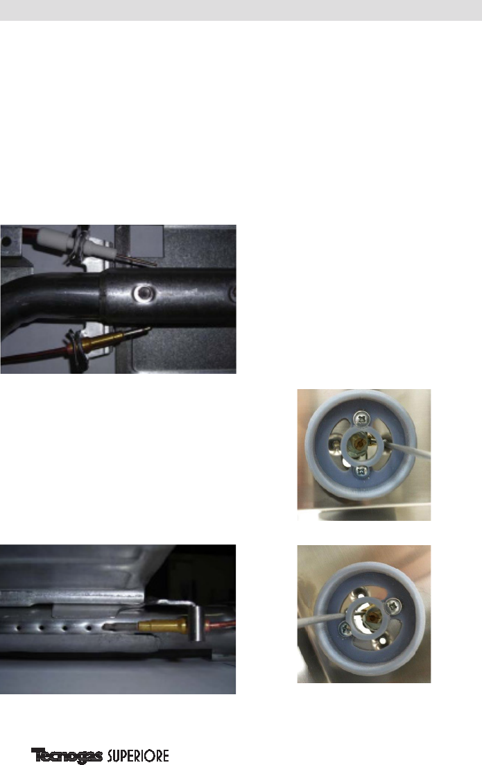
SURFACE BURNERS
1. Light one burner at a time and set the
knob to the MINIMUM position
(small ame).
2. Remove the knob.
3. The range is equipped with a safety
valve. Using a small size slotted
screwdriver, locate the By-pass screw
valve on the valve body and turn it to
the right or left until the burner ame
is adjusted to desired minimum.
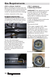
4. Make sure that the ame does not go
out when switching quickly from the
MAXIMUM to the MINIMUM position.
For all hob burners
For simmer burners, on the tap in the right