461308472 INSTALLATION MANUAL FOR 48’’ GAS RANGES
Table of Contents Warnings & Important Safety Instructions Dimensions Specifications Technical data Clearance Dimensions (Proximity to Cabinets) Clearance Dimensions (Wood/Composite Overlay) Electrical & Gas Requirements General Information Installation/ Door Removal Leg Installation/Adjustments/Alignments Anit-tip Device Installation Connecting Gas & Electrical Final Preparation Performance Checklist Service & Registration Warranty USA WARNING: If the information in this manual is not followed exa
Warnings & Important Safety Instructions • Before beginning, please read these instructions completely and carefully. • DO NOT remove permanently affixed labels, warnings, or plates from product. This may void the warranty. • All local and national codes and ordinances must be observed. Installation must conform with local codes or in the absence of codes, the National Fuel Gas Code ANSIZ223.1 INFPA54.
Warnings & Important Safety Instructions A GFI shall be used if required by NFPA-70 (National Electric Code), federal/state/local laws, or local ordinances. •The required use of a GFI is normally related to the location of a receptacle with respect to any significant sources of water or moisture. •TECNOGAS SUPERIORE will NOT warranty any problems resulting from GFI outlets which are not installed properly or do not meet the requirements below.
Warnings & Important Safety Instructions DANGER CHEMICAL HAZARD To avoid risk of property damage and/or personal injuryor death; this appliance is not too be used as a heating source. • Benzene is a chemical which is part of the gas supply to this cooking product, which is consumed in the flames during combustion. Exposure to a small amount of benzene is possible if a gasleak occurs. Formaldehyde and soot are by products of incomplete combustion.
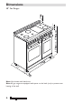
33" Dimensions 35" 7/8 min - 37" 5/16 max 2" 1" 3/8 48” Gas Ranges 23 47 8 "7 / " 2" 3 / 16 Note: Unit shown with island trim. Note: All gas ranges are equipped with spacer on the back (25/64) to prevent over heating of the wall.
Dimensions 48” Gas Ranges 47" 7/8 47" 7/8 2" 1" 3/8 1" 3/8 5" 25" 33" Gas 2" 1/8 Electricity 2" 5" 9/16 26" 7/8 2" 3/16 1" 3/8 3/8" 2" 27/64 35" 15/32 min - 36" 7/8 max 2" 1/8 5" 1" 11/32 2" 3/8 3/8" 2" 6/8 1" 1/2 23" 1" 11/32 2" 6/8 min 4" 1/4 max 35" 7/8 min - 37" 5/16 max 2" 7
Specifications Technical data Burners - injectors and volume Range Mod. ...482... Methane 4’’ Burners LPG 10’’ By-pass Inj. W BTU/h Inj. W BTU/h Ø W BTU/h Small burner 92 1055 3600 56 1055 3600 28 322 1100 Medium burner 117 1661 6500 70 1661 6500 34 381 1300 Large burner 155 2931 11000 93 2931 11000 44 791 2700 5275 18000 82 (2) 50 5275 18000 65 1377 4700 18000 82 (2) 50 18000 60 27 1377 4700 Power burner Ext. ring Int.
Specifications Technical data Induction and Burners - injectors and volume Range Mod. ...483... Methane 4’’ Burners Medium burner LPG 10’’ By-pass Inj. W BTU/h Inj. W BTU/h Ø W BTU/h 117 1661 6500 70 1661 5700 34 381 1300 Power burner Ext. ring Int. ring 137 (2) 80 5275 18000 82 (2) 50 5275 18000 65 1377 4700 Power burner with simmer Ext. ring Int.
Clearance Dimensions (Proximity to Cabinets) •This range may be installed directly adjacent to existing 36″ (91.4 cm) high base cabinets. 48 ″ IMPORTANT: The side trim MUST be 3/8” (0.95 cm) above the adjacent base cabinet countertop. This can be accomplished by raising the unit adjusting the legs. • The range CANNOT be installed directly adjacent to sidewalls, tall cabinets, tall appliances, or other side vertical surfaces above 36″ (91.4 cm) high. There must be a minimum of 6” (15.
Clearance Dimensions (Wood/Composite Overlay) The bottom of a standard hood should be 30 ‘‘ (76.2 cm) min to 36 ‘‘ (91.4 cm) max to above the countertop. This would typically result in the bottom of the hood being 66” (167.6 cm) to 72” (182.9 cm) above the floor. Refer to the range hood installation instructions for additional information. These dimensions provide for safe and efficient operation of the hood. Important: This range comes standard with 4’’ backguard.
Electrical & Gas Requirements Electrical Requirements Check your national and local codes regarding this unit. The ranges series RN482... and RD482... require120VAC/60 Hz; 4 ft. (121.9 cm), 3-wire cord with grounded 3-prong plug NEMA 5-15 attached to unit. The ranges series Rn483 require 120/240 Vac 60 Hz, 4 ft. (121.9 cm), 4-wire cord with grounded 4-prong plug NEMA 14-50 attached to unit. See “Electrical Connection” section for grounding instructions. Must be fused seperately from any other circuit.
Gas Requirements TO INSTALL PRESSURE REGULATOR 1: Remove the 2 covers on the back of the 3 - Screw the assembled pressure regurange unscrewing the 3 screws indicated lator on the range like shown on picture below. Pay attention to the vertical aligneon below pictures. ment of the same pressure regulator. COVERS SCREWS 2 - Take from the top of packaging the parts shown in the picture below to assemble the pressure regulator. 4 - Re-install the covers previously removed.
Gas Requirements Flexible Connections: If the unit is to be installed with flexible couplings and/or quick-disconnect fittings, the installer must use a heavy-duty AGA design-certified flexible connector or at least1/2” (1.3 cm) ID NPT (with suitable strainreliefs) in compliance with ANSI Z21.41and Z21.69. G - area for gas connection E - area for electric connection 14 In Canada: CAN 1-6, 10-88 metal connectors for gas appliances and CAN 1-6.9 M79 quick disconnect devices for use with gas fuel.
Gas Requirements GAS CONVERSION WARNING! Before carrying out this operation, disconnect the appliance from gas and electricity. Gas conversion shall be conducted by a factory-trained professional. Call the customer service hotline to identify a factory-trained professional near your home. The gas conversion procedure for this range includes 6 steps: 1. Pressure regulator 2. Surface burners 3. Main oven burner 4. Broiler burner 5.Visual checks prior to closure of oven bottom panel 6.
Gas Requirements STEP 2: SURFACE BURNERS To replace the nozzles of the surface burners, lift up the burners and unscrew the nozzles shipped with the range using a 7 mm (sochet wrench). Replace nozzles using the conversion set supplied with the range or by a Tecno authorized parts warehouse. Each nozzle has a number indicating its flow diameter printed on the body. Consult the table on “Specifications Technical data “ paragraph for matching nozzles to burners.
Gas Requirements STEP 4: BROILER BURNER (MAIN) Loosen the 2 screws on left and right sides and pull out the burner from its support burner from its support. ATTENTION: pay extra attention to avoid damage to the igniter and thermocouple. STEP 5: BROILER BURNER (auxiliary) To replace the noozle of the small oven burner start by removing the bottom panel Using a 7 mm or 10 mm sochet wrench to unscrew the nozzle.
Gas Requirements STEP 6:VISUAL CHECKS Before reinstalling the bottom panel, the following visual check must be performed to ensure that the conversion has been carried out properly and without damage to other components of the range. BURNER IGNITER AND THERMOCOUPLE POSITION The appropriate gap between the tip of the spark plug or thermocouple and the burner shall be approximately 1/8’’.
General Information READ AND FOLLOW ALL WARNING AND CAUTION INFORMATION WHEN INSTALLING THIS APPLIANCE. Remove the burner grates and styrofoam off the top cooking surface. Be sure to remove the burner caps packaged in styrofoam below the burner grates. • All openings in the wall behind the appliance and in the floor under the appliance must be sealed. Do not discard the anti-tip metal bracket supplied with the range.This is the anti-tip device and must be installed with the unit.
Installation/Door removal NOTICE DO NOT use the handle or oven door to lift the oven. DO NOT lift or carry the door by the handle. Removing the door must be done by your dealer, a qualified licensed plumber, or certified gas installer Door Removal 1)- Open the door completely. Place the pins, supplied with unit, in pin hole. For personal safety, ONLY use pins supplied with the unit. 3)- Lift the door up and extract.
Leg Installation/Adjustments/Alignment Tecnogas ranges must be used only with the legs properly installed. Six height adjustable legs are delivered with the range in the polysterene container situated over the appliance. Before installing the legs, position the appliance near its final location as the legs are not suitable for moving the appliance over long distances. After unpacking the range, raise it enough to insert the legs in the appropriate receptacles situated on the lower part of the appliance.
Anti-tip Device Installation HAZARD: To reduce the risk of property damage or personal injury; install anti-tipping device provided in accordance with the installation instructions in this document. Device must be engaged properly to prevent product from tipping over. Kit enclosed with the range. Mark and drill holes where the bracket will be located. TIPPING Measure from floor to the anti-tip bar located in a slit on the back of the range.
Connecting Gas & Electric DANGER GAS LEAK HAZARD To avoid risk of personal injury or death; leak testing of the appliance must be conducted according to the manufacturer’s instructions. Before placing appliance in operation, always check for gas leaks with soapy water solution. • DO NOT USE AN OPEN FLAME TO CHECK FOR GAS LEAKS. Connect gas and electrical. Before placing appliance in operation, always check for gas leaks.
Final Preparation •All stainless steel body parts should be wiped with hot, soapy water and with a liquid cleaner designed for this material. If buildup occurs, DO NOT use steel wool, abrasive cloths, cleansers, or powders! If it is necessary to scrape stainless steel to remove encrusted materials, soak with hot, wet cloths to loosen the material, then use a wool or nylon scraper.
Performance Checklist Rotary switch knob OFF = Closed position = Oven light on = Oven light on - fan = Fan LEFT CAVITY Gas oven switch knob range 48’’ OFF = Closed position from MIN to MAX = Oven temperatures (300-450 °F) Broil = Broil RIGHT CAVITY Gas oven switch knob range 48’’ OFF from MIN to MAX = Closed position = Oven temperatures Electric griddle knob range 48’’ OFF from 1 to 7 positions = Closed position = Griddle temperatures 25
Performance Checklist Induction zone knob OFF A Cooking zone Off (not activated) = Accelerated heat-up = Turbo Boost/Bridge from 1-9 = Induction power levels = Induction special functions: Melting, Warming, Simmering 26
Service & Registration Only authorized replacement parts may be used in performing service on the appliance. All servicing should be referred to a qualified technician. Contact TECNOGAS SUPERIORE 1-844-322-2111, for the nearest service parts distributor in your area or write to: CUSTOMERCARE@TECNOSPA.IT Record the information indicated below. You will need it if service is ever required. The model and serial number can be found by looking in the last page of this booklet.
WARRANTY U.S.A Please record your model (MOD) and serial number (S/N) below for future reference. For your convenience, a label containing this information is supplied with this booklet.
WARRANTY U.S.A 6) Any repair, modification, alteration, or adjustment provided by any person not authorized by TECNOGAS SUPERIORE. 7) Failure of the product if it is abused, misused or used for other than the intended purpose or if used commercially/industrially. 8) Incorrect electric current, voltage or power supply. 9) Improper setting of any control. 10) Replacement of house fuses or resetting of circuit breakers. 11) Replacement of the light bulbs.
CONVERSION LABEL INSTALLATION LABEL Labels
461308472 tecnogassuperiore.