
User`s manual

5-18
A+ SERVER 1022G-NTF User's Manual
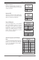
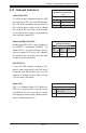
UID Button
Pin Defi nitions
Pin# Defi nition
1 Ground
2 Ground
3 Button In
4 Ground
Unit Identifi er Button
In addition to the UID (Unit Identifi er) button
on the rear I/O panel, there is another UID
button located on the control panel. When
you push either UID button, both Rear UID
and Front Panel UID Indicators will illumi-
nate. Push either button again to turn off
both indicators. These UID indicators provide
easy identifi cation of a system unit that may
be in need of service.
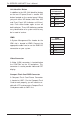
IPMB
A System Management Bus header for the
IPMI slot is located at IPMB. Connect the
appropriate cable here to use the IPMB I2C
connection on your system.
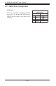
IPMB
Pin Defi nitions
Pin# Defi nition
1 Data
2 Ground
3 Clock
4 No Connection
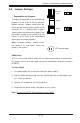
Video Connector
A Video (VGA) connector is located below
the COM Port on the IO backplane. This
connector is used to provide video and CRT
display.
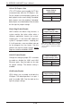
Compact Flash Card PWR Connector
A Compact Flash Card Power Connector
is located at JWF1. For the Compact Flash
Card to work properly, you will need to en-
able with JCF1 and connect a Compact Flash
Card power cable to JWF1 fi rst.