
User`s manual


6-2
A+ SERVER 1022G-NTF User's Manual
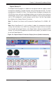
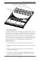
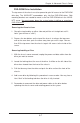
Figure 6-1. Chassis: Front and Rear Views
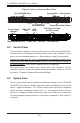
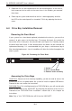
6-2 Control Panel
The control panel (located on the front of the chassis) must be connected to the JF1
connector on the serverboard to provide you with system status indications. These
wires have been bundled together as a ribbon cable to simplify the connection.
Connect the cable from JF1 on the serverboard to the appropriate header on the
Control Panel PCB (printed circuit board). Make sure the red wire plugs into pin 1
on both connectors. Pull all excess cabling out of the airfl ow path.
The control panel LEDs inform you of system status. See "Chapter 3: System
Interface" for details on the LEDs and the control panel buttons. Details on JF1 can
be found in "Chapter 5: Advanced Serverboard Setup."
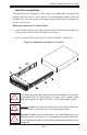
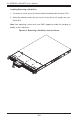
6-3 System Fans
Four 4-cm heavy duty counter-rotating fans provide the cooling for the A+ SERVER
1022G-NTF. Each fan unit is actually made up of two fans joined back-to-back, which
rotate in opposite directions. This counter-rotating action generates exceptional
airfl ow and works to dampen vibration levels. It is very important that the chassis
top cover is properly installed and making a good seal in order for the cooling air
to circulate properly through the chassis and cool the components. See Figure 6-2
for details..
System Reset
Control PanelSystem LEDs
Main Power Hard Drive Bays
Slim DVD-ROM Drive
Power Supply
Modules
PCI Expansion Slots
(w/ Riser Cards)
Mouse/Keyboard Ports
USB
Ports
COM1 Port VGA Port Ethernet Ports
IPMI LAN
Port