
User`s manual


Chapter 5: Advanced Motherboard Setup
5-17
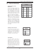
Power Button
The Power Button connection is
located on pins 1 and 2 of JF1.
Momentarily contacting both pins
will power on/off the system. To turn
off the power when set to suspend
mode, press the button for at least
4 seconds. Refer to the table on the
right for pin defi nitions.
5-9 Connector Defi nitions
Optional Connection
Power Button
Pin Defi nitions (JF1)
Pin# Defi nition
1 Power Signal
2 Ground
Auxilliary Power Connector
The 4-pin processor power connec-
tor (JP3) is used to provide power to
external devices such as hard disks &
CD-ROM drives. This power connec-
tor supports 12V and 5V devices.
4-Pin External Power
Connector
Pin Defi nitions
Pin# Defi nition
1 +12V
2 Ground 1
3 Ground 2
4 +5V
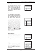
20-pin Proprietary Power
Connectors
There are two 20-pin main power sup-
ply connectors (JWR3, JWR4) and a
4-pin auxiliary power connector (JP3)
on the motherboard. For the power
supply to work properly, please follow
the instructions given below. See the
table on the right for pin defi nitions.
Note: You cannot use both JWR3 and
JWR4 at the same time. Only one
connector can be used for input power
supply to the motherboard at a time.
For proper use of the proprietary PWR
connectors, please customize your
PWR cables based on the SMC PWR
connector pin-out defi nitions shown
in the table.
20-pin Main Power Connector
Pin Defi nitions
Pin# Defi nition Pin# Defi nition
11 PS On 1 Ground
12 5VSB 2 Ground
13 Ground 3 Ground
14 Ground 4 Ground
15 Ground 5 Ground
16 NC2 6 NC1
17 12V 7 12V
18 12V 8 12V
19 12V 9 12V
20 12V 10 12V