
User`s manual


5-18
SUPERSERVER 2016Ti-HTRF User's Manual
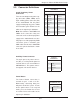
Reset Button
The reset button (from the computer
chassis) connects to pins 3 and 4 of
JF1. See the table on the right for pin
defi nitions.
Reset Button
Pin Defi nitions (JF1)
Pin# Defi nition
3 Reset
4 Ground
Power Fail LED
The Power Fail LED connection is
located on pins 5 and 6 of JF1. Re-
fer to the table on the right for pin
defi nitions.
PWR Fail LED
Pin Defi nitions (JF1)
Pin# Defi nition
5 Vcc
6 Ground
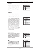
Overheat (OH)/Fan Fail/Front UID
LED
Connect an LED cable to the Front
UID and OH/Fan Fail connections on
pins 7 and 8 of JF1 to display UID
(Unit ID) signals or to provide ad-
vanced warnings for chassis overheat/
fan failure. Refer to the table on the
right for pin defi nitions.
OH/Fan Fail LED
Pin Defi nitions (JF1)
Pin# Defi nition
7 Vcc/Blue UID LED
8 OH/Fan Fail LED
NIC1/2 LED
Pin Defi nitions (JF1)
Pin# Defi nition
9/11 Vcc
10/12 Ground
NIC1/NIC2 (LAN1/LAN2)
The NIC (Network Interface Control-
ler) LED connection for LAN port 1
is located on pins 11 and 12 of JF1,
and the LED connection for LAN Port
2 is on Pins 9 and 10. These are
2-pin NIC LED headers. Attach LED
cables to the respective pins to display
network activities for LAN1 and LAN2.
Refer to the table on the right for pin
defi nitions.
OH/Fan Fail Indicator
Status
State Defi nition
Off Normal
On Overheat
Flashing Fan Fail
HDD LED
The HDD LED connection is located
on pins 13 and 14 of JF1. Attach a
hard drive LED cable here to display
HDD activity (for any hard drive activ-
ity on the system). See the table on
the right for pin defi nitions.
HDD LED
Pin Defi nitions (JF1)
Pin# Defi nition
13 +3.3V
14 HD Active