
User's Manual


Chapter 5: Advanced Motherboard Setup
5-13
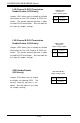
370SSE+ Quick Reference (5010E only)
Jumpers Description Default Setting
JP11/12 Front Side Bus Speed Both: Pins 1-2 (Auto)
JP31 LAN2 Enable/Disable Closed (Enabled)
JP32 Speaker En/Disable Closed (Enabled)
JP33 LAN1 Enable/Disable Pins 1-2 (Enabled)
JPWAKE Keyboard Wake-Up Pins 1-2 (Disabled)
Connectors Description
COM1/COM2 COM1/COM2 Serial Port Connector
CPU/CH/OH FAN CPU/Chassis/Overheat Fan Headers
J1, J2, J3 Memory (DIMM) Slots
J18, J19 IDE Hard Disk Drive Connectors
JP26 Floppy Disk Drive Connector
J29 ATX Power Connector
J30 PS/2 Keyboard/Mouse
J32, J33,J43,J51 Universal Serial Bus Ports
JF1 Front Control Panel
JL1 Chassis Intrusion Header
JOH Overheat LED
JWOR Wake-On-Ring Header
LAN1/LAN2 Ethernet Port 1/2
VGA VGA Port (monitor)
WOL Wake-on-LAN Header
Also see the figures on pages 5-4, 5-5 for the I/O ports the Front
Control Panel (JF1) connectors.
Jumpers not indicated are for test purposes only.
(*Please refer to Sections 5-8, 5-9, and 5-10 for detailed informa-
tion on jumper settings and pin definitions.)