
User`s manual


Chapter 5: Advanced Serverboard Setup
5-13
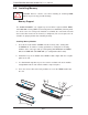
Reset Connector
The reset connector is located on pins
3 and 4 of JF1 and attaches to the
reset switch on the computer chas-
sis. See the table on the right for pin
defi nitions.
PW_ON Connector
The PW_ON connector is on pins 1
and 2 of JF1. This header should be
connected to the chassis power but-
ton. See the table on the right for pin
defi nitions.
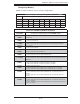
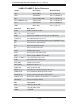
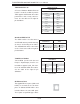
5-9 Connector Defi nitions
Required Connection
+12V 8-pin Power
Pin Defi nitions
Pins Defi nition
1 - 4 Ground
5 - 8 +12V
ATX Power 24-pin Connector
Pin Defi nitions
Pin# Defi nition Pin # Defi nition
13 +3.3V 1 +3.3V
14 -12V 2 +3.3V
15 COM 3 COM
16 PS_ON 4 +5V
17 COM 5 COM
18 COM 6 +5V
19 COM 7 COM
20 Res (NC) 8 PWR_OK
21 +5V 9 5VSB
22 +5V 10 +12V
23 +5V 11 +12V
24 COM 12 +3.3V
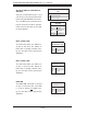
Reset Button
Pin Defi nitions (JF1)
Pin# Defi nition
3 Reset
4 Ground
Power Button
Pin Defi nitions (JF1)
Pin# Defi nition
1 PW_ON
2 Ground
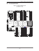
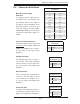
Processor Power Connector
The power supply must be connected
to any three of the JPW1, JPW2 and
JPW4 and JPW5 power headers.
See the table on the right for pin
defi nitions.
Main ATX Power Supply
Connector
The primary power supply connec-
tor (JPW3) meets the SSI EPS 12V
specifi cation. Refer to the table on
the right for the pin defi nitions of the
ATX 24-pin power connector. You
must also connect the 8-pin (JPW1/
JPW2/JPW4/JPW5) processor power
connectors to your power supply (see
below).
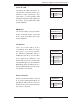
Power Fail LED
The Power Fail LED connection is lo-
cated on pins 5 and 6 of JF1. See the
table on the right for pin defi nitions.
PWR Fail LED
Pin Defi nitions (JF1)
Pin# Defi nition
5 3.3V
6 PWR Supply Fail